Installation guide
Thermostatic valve
Type BVTS
© Danfoss A/S (AC-MCI / jmn), 2013-11 IC.PI.500.E5.72 / 520B5748 1
003R9003
003R9003
Dansk
English
max. 10 bar
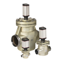
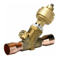
Fig. 1 Fig. 2 Fig. 3
0035
PED 97/23/EC cat. IV
EN 14597 (DIN 3440)
Application
The thermostatic valve BVTS is designed for
protection of biomass boilers and re stoves.
It prevents overheating of the boiler by
discharging water from heat generator or
condensing coil.
The valve is used also to prevent
back-burning in the fuel store by ooding
the fuel in case of excessive temperature.
Technical Data
Media: Water
Opening temperature: 95 °C ± 2 °C
(xed)
Max. sensor temperature: 125 °C
Flow capacity: 2.6 m
3
/h
(∆p = 1bar)
Connection size: G ¾ pipe thread
(ISO-228)
Dimensions in [mm], (g. 1)
Installation
Installation of BVTS valve on boiler with
safety heat exchanger A (g. 2).
Installation of BVTS valve in back-burning
application B (g. 2) .
Before installation of the valve ush the
system to make sure that there are no
impurities which might deposit on the valve
seat and cause malfunction.
Remember to install a lter ahead of the
valve. (Fig. 3).
The sensor can be mounted in any position.
Make sure the whole sensor is in contact
with the controlled area.
The arrow on the valve body shows
direction of ow. When installing the valve,
make sure it is positioned properly.
Max torque for sensor pocket mounting is
30 Nm.
Only cooling applications:
After installation the proper function of the
valve should be checked by heating up the
system.
Service
It is recommended to check proper function
of the valve once a year by qualied
personnel. Functional check is carried out
manually by depressing the red button that
opens the ow on the valve.
It is not allowed to lose red button as it will
cause product malfunction.
Tekniske data
Medier: Vand
Åbningstemperatur: 95 °C ± 2 °C (fast)
Maks. følertemperatur: 125 °C
Flowkapacitet: 2.6 m
3
/h
(∆p = 1bar)
Tilslutningsstørrelse: G ¾ Rørgevind
(ISO-228)
Dimensioner [mm], (g. 1)
Installation
Installation af BVTS-ventilen på kedel med
sikkerhedsvarmeveksler A (g. 2).
Installation af BVTS-ventil som
brandbeskyttelse B (g. 2).
Før installation af ventilen skal systemet
skylles igennem for at sikre, at der ikke
ndes urenheder, der kan aejres på
ventilsædet og forårsage fejlfunktion.
Husk at installere et lter foran ventilen.
(Fig. 3).
Føleren kan installeres i en hvilken som
helst position. Sørg for, at hele føleren er
i kontakt med det kontrollerede område.
Pilen på ventilenheden viser owets
retning. Når ventilen installeres, skal sikres,
at den er placeret korrekt. Maks. moment
for føler lomme er 30Nm.
Kun køleformål:
Efter installation skal ventilens korrekte drift
kontrolleres ved at varme systemet op.
Service
Det anbefales, at kvaliceret personale en
gang om året kontrollerer ventilens korrek-
te drift. Funktionel kontrol udføres manuelt
ved at trykke på den røde knap, som åbner
owet på ventilen.
Forskruningen der holder den røde test
knap, må ikke løsnes, da dette vil medføre
funktionsfejl.
ø16
B
A
Anvendelse
Den termostatiske ventil BVTS er konstrueret
til beskyttelse af biomassekedler og
brændeovne. Den forhindrer overhedning af
kedlen ved at udlede vand fra varmege
neratoren eller kondensatorspolen.
Ventilen anvendes også til at undgå brand
i brændstoageret ved at oversprøjte
brændstoet med vand, hvis temperaturen
bliver for høj.