DEVItector™ II V2User Guide
BC421332622232en-010101 2022.07 | FEC | ©Danfoss | 9
Inside the HVU cabinet
Fig. 11: Protective earth logo located on the inside of
the HVU close to the common ground.
High voltage Outlet Cables
HIGH VOLTAGE
10 kV~ / 400 V⎓
Fig. 12: High voltage Outlet Cables marking.
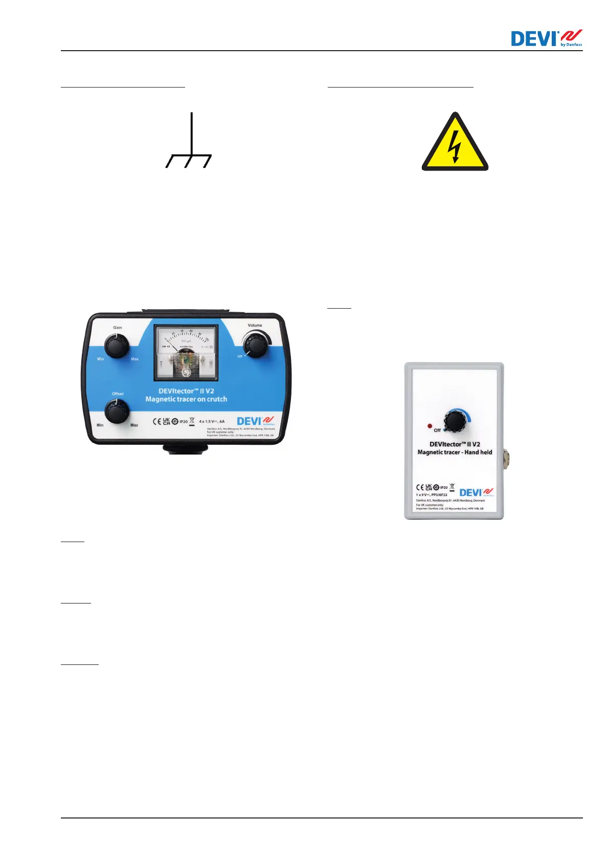
User Interface of Magnetic tracer on crutch
Fig. 13: Control panel of the large Magnetic tracer on
crutch unit.
Control items are explained below.
Gain:
Controls the amplication of the sensor signal as
shown on the meter. Turn clockwise to increase, and
counterclockwise to decrease amplication.
Oset:
The regulator “zero balance” allows in some cases to
compensate for induction of a signal reected by the
pointer indicator.
Volume:
Controls the acoustic amplication of the
sensor signal. Turn clockwise to increase, and
counterclockwise to decrease amplication.
User interface of Magnetic tracer - Hand held
Gain:
Controls the amplication of the sensor signal as
shown on the meter. Turn clockwise to increase, and
counterclockwise to decrease amplication.
Fig. 14: Control panel of the small Magnetic tracer - Hand
held unit.
Tracers safety
Both Tracer units are battery powered and contains
only safe voltage. Can only be used together with
DEVItector™ burner unit while in trace mode.