Installation Guide DLX seriesL00410622-01 11
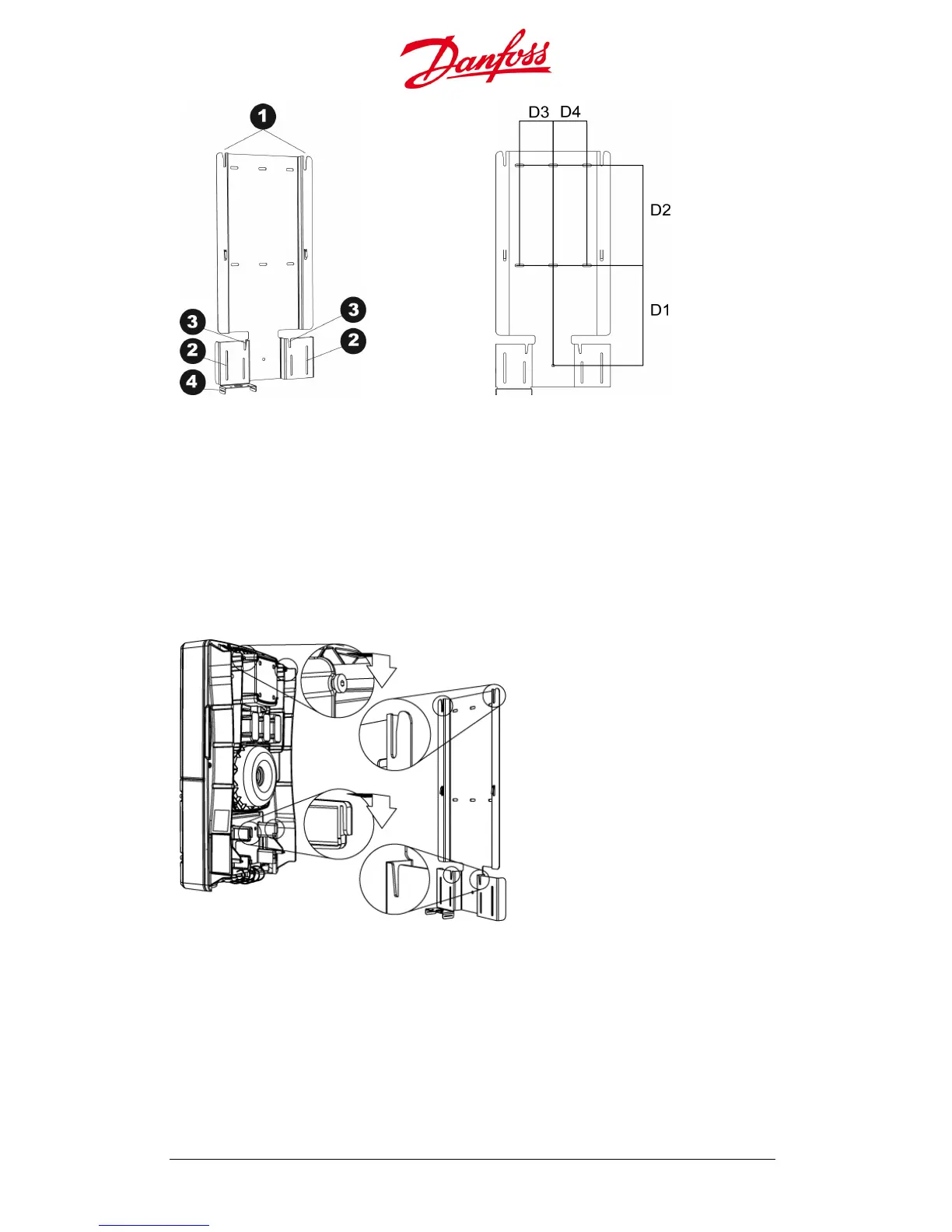
Figure 2.2.2: Inverter bracket
1. Carrier slots for the inverter
2. Steering slots for the inverter
3. Carrier slots for the Stringbox
4. Fixing clip
Figure 2.2.3: Distances between fixing screws
D1. 232.5 mm
D2. 232.5 mm
D3. 75 mm
D4. 75 mm
2.2.2. Inverter
Attach the inverter to the mounting bracket as follows:
Figure 2.2.4: Hooks on the back of the inverter
• Locate the hooks for the carrier
slots on the upper back and the
hooks for the steering slots on the
lower back of the inverter.
• Use the locating pins on the
Stringbox.