Installation Guide DLX seriesL00410622-01 7
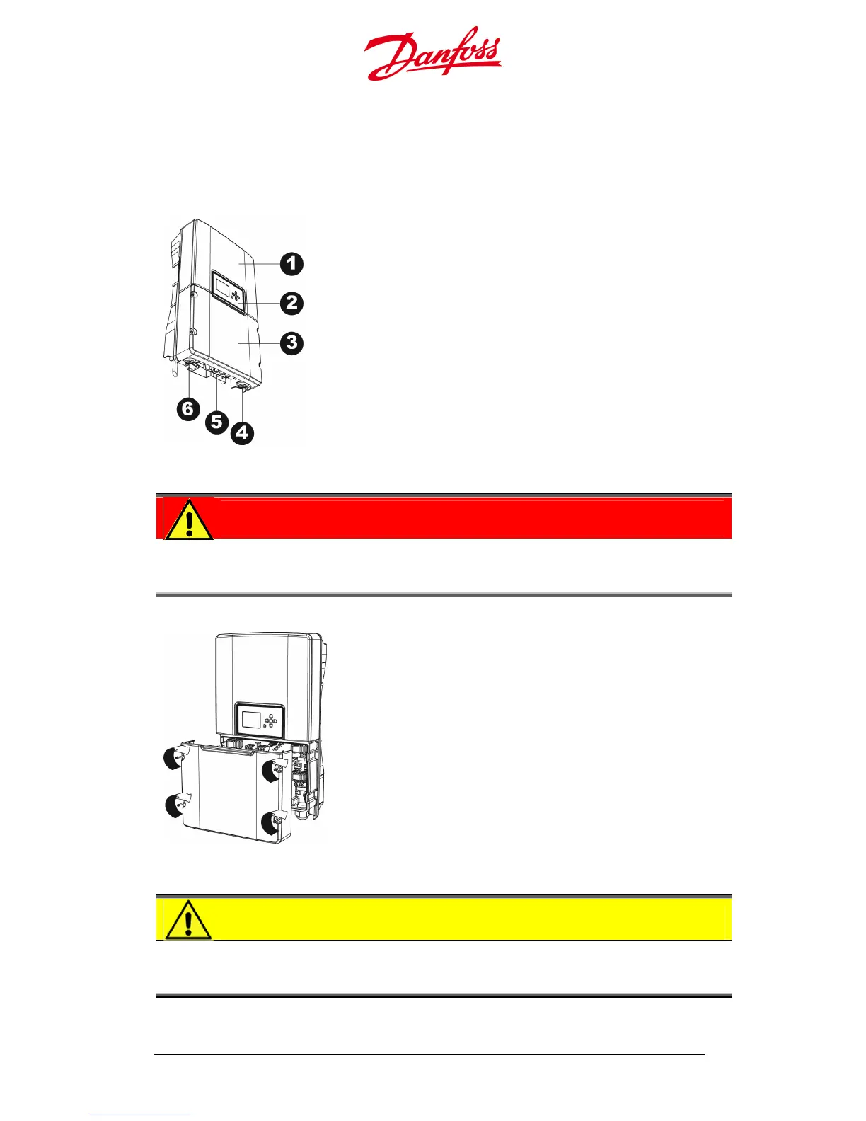
The front surface of the inverter consists of an upper and a lower cover.
The upper cover may only be removed by Danfoss authorized personnel. Removal of the
upper cover by unauthorized persons voids the warranty!
The lower cover protects the connection area, and may be removed by the system
installer for electrical connection and maintenance of the inverter.
Figure 1.3.4: Inverter structure
1. Upper cover
2. User Interface
3. Lower cover; customer connection area
4. AC output
5. DC input
6. Network input
DANGER
Always disconnect the PV array cables from the inverter after turning the AC and
DC OFF, but before removing the covers, as the PV array can supply up to 600 VDC
to the inverter when exposed to sunlight.
Fi
gure 1.3.5: Lower cover
• Loosen the four screws on the lower cover
with a 4 mm hex key, according to the
figure.
• Take the cover off carefully.
• Store the lower cover and screws safely to
avoid loss or damage.
• Fasten the screws on the lower cover with
a torque of 1.0 Nm.
CAUTION
Never remove the inverter lower cover in wet conditions! Removal of the inverter
lower cover during rain or in damp conditions can damage sensitive internal
electronic components.