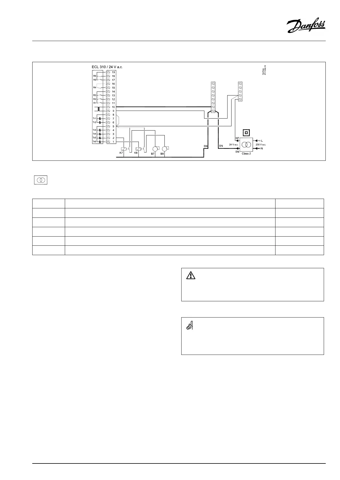
ApplicationA375.2/A375.3(burnersteps7–8)
Double-insulated(two-chamber)transformer
Terminal
Description
Max.load
5
Phaseforcontrolofburnersteps7and8
4
Connectionformotorizedcontrolvalve-opening,circuit2(A375.3)
1A/24Va.c.
3
Connectionformotorizedcontrolvalve-closing,circuit2(A375.3)
1A/24Va.c.
2
K7
Auxilliaryrelayforcontrolofburnerstep7
1A/24Va.c.
1
K8
Auxilliaryrelayforcontrolofburnerstep8
1A/24Va.c.
Donotconnect230Va.c.poweredcomponentstoa24Va.c.power
suppliedcontrollerdirectly.Useauxilliaryrelays(K)toseparate230
Va.c.from24Va.c.
Wirecrosssection:0.5-1.5mm²
Incorrectconnectioncandamagetheelectronicoutputs.
Max.2x1.5mm²wirescanbeinsertedintoeachscrewterminal.
VI.GU.L2.02
©Danfoss|2017.09|69
OperatingGuideECLComfort210/296/310,applicationA275/A375
 Loading...