2.5.5Electricalconnections,Pt1000temperaturesensorsandsignals
A275:
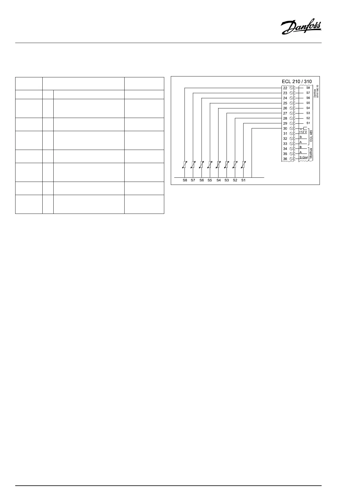
TerminalSensor/description
Type
(recomm.)
29and30
S1
Outdoortemperaturesensor*
ESMT
28and30
S2
A275.3only:
Returntemperaturesensor,
circuit2
ESM-11/ESMB/
ESMC/ESMU
27and30
S3
Boilertemperaturesensor**,
circuit1
ESMU/ESMB
26and30
S4
A275.3only:
Flowtemperaturesensor**,
circuit2
ESM-11/ESMB/
ESMC/ESMU
25and30
S5
Returntemperaturesensor,
circuit1
ESM-11/ESMB/
ESMC/ESMU
24and30
S6
A275.2/A275.3only:
DHWtanktemperaturesensor,
circuit2/3
ESM-11/ESMB/
ESMC/ESMU
23and30
S7Roomtemperaturesensor***,
circuit1
ESM-10
22and30
S8
A275.3only:
Roomtemperaturesensor***,
circuit2
ESM-10
*
Iftheoutdoortemperaturesensorisnotconnectedorthe
cableisshort-circuited,thecontrollerassumesthatthe
outdoortemperatureis0(zero)°C.
**
Theboiler/flowtemperaturesensormustalwaysbe
connectedinordertohavethedesiredfunctionality.Ifthe
sensorisnotconnectedorthecableisshort-circuited,the
motorizedcontrolvalvecloses(safetyfunction).
***
Onlyforroomtemperaturesensorconnection.Theroom
temperaturesignalcanalsobeavailablefromaRemote
ControlUnit(ECA30/31).See'Electricalconnections,ECA
30/31'.
Factoryestablishedjumper:
30tocommonterminal.
70|©Danfoss|2017.09
VI.GU.L2.02
OperatingGuideECLComfort210/296/310,applicationA275/A375
 Loading...