© Danfoss | Climate Solutions | 2023.10
AN269954243889en-000905 | 14
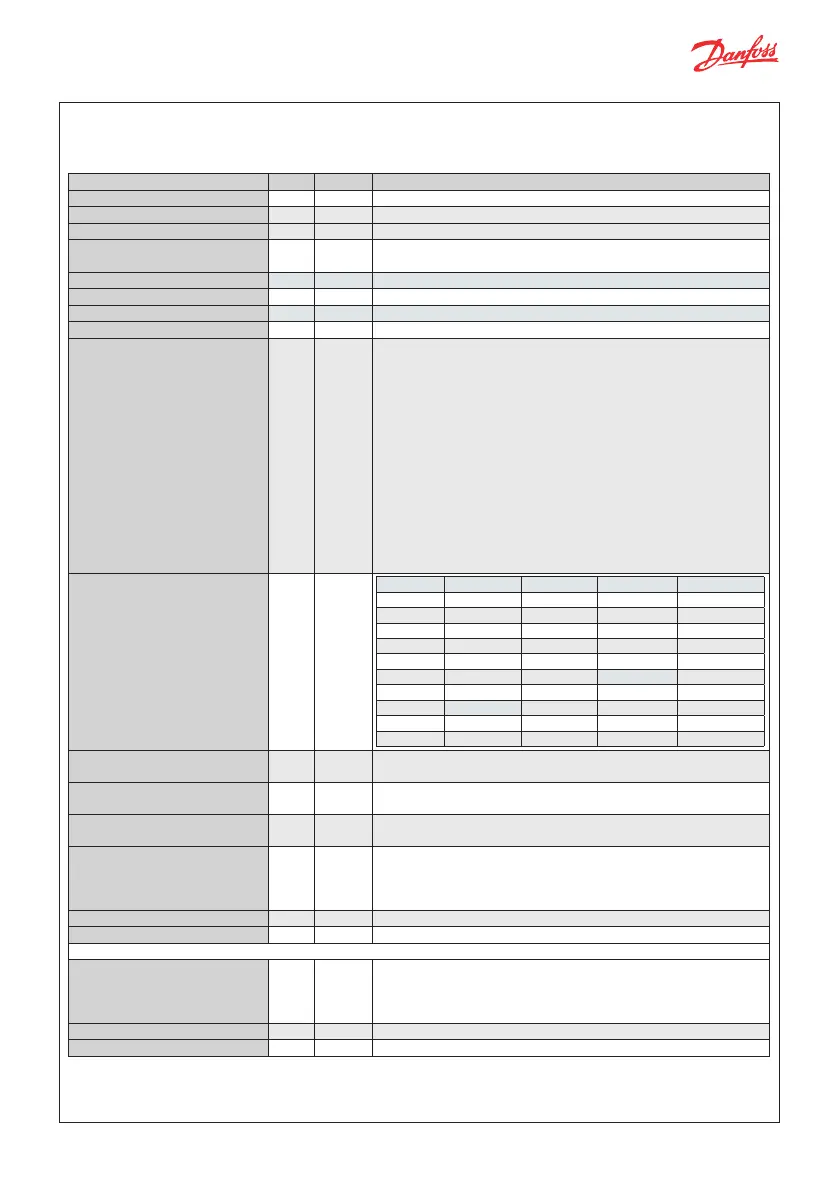
Parameter PNU Default Description
R012 Main switch 3001 0 0 = regulation O | 1 = regulation On
R102 Operation mode 3002 0 0 = Superheat control | 1 = Valve driver
O002 DI1 conguration 3101 1 0 = Bus->Start/Stop | 1 = Main Switch
I033 Driver reference
conguration
3131 0 0 = Voltage to OD | 1 = Modbus to OD | 2 = Modbus to steps | 3 =
Current to OD
I034 Ext ref. voltage low 3130 0 Range 0 – 10 V. To be used with I033
I035 Ext ref. voltage high 3129 10 Range 0 – 10 V. To be used with I033
I036 Ext ref. current low 3128 4 Range 0 – 20 mA. To be used with I033
I037 Ext ref. current high 3127 20 Range 4 – 20 mA. To be used with I033
I067 Valve conguration 3132 0
0
= no valve, 1 = UserDef
2 = ETS 12C, 3 = ETS 24C, 4 = ETS 25C, 5 = ETS 50C, 6 = ETC 100C
7 = ETS 6, 8 = ETS 12.5, 9 = ETS 25, 10 = ETS 50, 11 = ETS 100,
12 = ETS 250, 13 = ETS 400
14 = KVS 2C, 15 = KVS 3C, 16 = KVS 5C
17 = KVS 15, 18 = KVS 42
19 = CCMT 0, 20 = CCMT 1
21 = CCMT 2, 22 = CCMT 4, 23 = CCMT 8, 24 = CCMT 16, 25 = CCMT 24,
26 = CCMT 30, 27 = CCMT 42
28 = CCM 10, 29 = CCM 20, 30 = CCM 30, 31 = CCM 40
32 = CTR 20
33 = CCMT 3L, 34 = CCMT 5L, 35 = CCMT 8L, 36 = CCMT 10L,
37 = ETS 175L, 38 = ETS 175L OFHT, 39 = ETS 250L,
40 = ETS 250L OFHT, 41 = ETS 400L, 42 = ETS 400L OFHT,
43 = ETS 500L, 44 = ETS 500L OFHT, 45 = ETS 8M Bipolar
O030 Refrigerant 3017 0
0 = Undef 10 = R503 20 = R407C 30 = R417A 40 = 448A
1 = R12 11 = R114 21 = R407A 31 = R422A 41 = 449A
2 = R22 12 = R142b 22 = R407B 32 = R413A 42 = 452A
3 = R134A 13 = R User 23 = R410A 33 = R422D 43 = R450A
4 = R502 14 = R32 24 = R170 34 = 427A 44 = R452B
5 = R717 15 = R227 25 = R290 35 = R438A 45 = R454B
6 = R13 16 = R401A 26 = R600 36 = R513A 46 = R1233zdE
7 = R13b1 17 = R507 27 = R600a 37 = R407F 47 = R1234zeZ
8 = R23 18 = R402A 28 = R744 38 = R1234ze 48 = R449B
9 = R500 19 = R404A 29 = R1270 39 = R1234yf 49 = R407H
50 = R469A
I040 S2 sensor conguration 3105 0
0 = Not dened | 1 = EKS 221 | 2 = ACCPBT NTC10K | 3 = MBT 153 10K |
4 = 112CP | 5 = Bus Shared | 6 = AKS
I041 S3 sensor conguration 3106 0
0 = Not dened | 1 = EKS 221 | 2 = ACCPBT NTC10K | 3 = MBT 153 10K |
4 = 112CP | 5 = Bus Shared | 6 = AKS
I042 S4 sensor conguration 3107 0
0 = Not dened | 1 = EKS 221 | 2 = ACCPBT NTC10K | 3 = MBT 153 10K |
4 = 112CP | 5 = Bus Shared | 6 = AKS
I043 Pe transmitter conguration 3108 0
0 = Not dened | 1 = AKS 32R | 2 = ACCPBP Ratio | 3 = 112CP |
4 = OEM Ratio | 5 = NSK | 6 = AKS 32 1 - 5V | 7 = OEM Voltage |
8 = Bus shared | 9 = AKS 32 1 - 6V | 10 = AKS 32 0 - 10V | 11 = AKS 33 |
12 = XSK | 13 = ACCPBP Current | 14 = OEM Current, 15=DST P110
O020 Pe transmitter min. (in bar g) 3115 -1 Dene pressure range in bar gauge
O021 Pe transmitter max. (in bar g) 3116 12 Dene pressure range in bar gauge
I044 Pc transmitter setup 3117 0
0 = Not dened | 1 = AKS 32R | 2 = ACCPBP Ratio | 3 = 112CP |
4 = OEM Ratio | 5 = NSK | 6 = AKS 32 1 - 5V | 7 = OEM Voltage |
8 = Bus shared | 9 = AKS 32 1 - 6V | 10 = AKS 32 0 - 10V | 11 = AKS 33 |
12 = XSK | 13 = ACCPBP Current | 14 = OEM Current
O047 Pc transmitter min. (in bar g) 3124 -1 Dene pressure range in bar gauge
O048 Pc transmitter max. (in bar g) 3125 34 Dene pressure range in bar gauge
EKE 1C – Commonly used parameter identication
PNU - equivalent to the Modbus register no. (Modbus address +1).
Actual value are read/written as 16-bit integer values without decimals. This is the default value as read via Modbus.
 Loading...