MAKING MODERN LIVING POSSIBLE
DKRCC.PS.RP0.A1.02/520H7142 ©Danfoss A/S (AC-MCI / sw), 2014-03
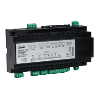
Manual
Superheat Controller,
type EKD 316
Advantages The superheat is regulated to the lowest
possible value.
The evaporator is charged optimally – even
when there are great variations of load and
suction pressure.
Energy savings – the adaptive regulation of
the refrigerant injection ensures optimum
utilisation of the evaporator and thus a high
suction pressure.
EKD 316 is a superheat controller for the
stepper motor valve that can be used where
there are requirements for accurate control of
superheat in connection with refrigeration.
The controller and valve can be used where
there are requirements for accurate control of
superheat in connection with refrigeration.
Applications:
Processing plant (water chillers)
Cold store (air coolers)
A/C plant
Heat pumps
Air conditioning
Regulation of superheat
MOP function
ON/OFF input for start/stop of regulation
Relay output to alarm
MOD bus communication
Safety features and
Alarm indications
Main features