©Danfoss A/S (AC-MCI / sw), 2014-03 DKRCC.PS.RP0.A1.02/520H7142 54 DKRCC.PS.RP0.A1.02/520H7142 ©Danfoss A/S (AC-MCI / sw), 2014-03
Manual Superheat controller type EKD 316Manual Superheat controller type EKD 316
Dimensions
Ordering
Type Function Code no.
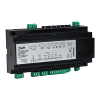
EKD 316
superheat controller
(with terminals)
084B8040
EKA 164A
Display
(with MODBUS communication)
084B8563
EKA 183A Programming key 084B8582
Supply voltage
24 V a.c./d.c. +/-15% 50/60 Hz, 10 VA
(the supply voltage is not galvanically
separated from the input and output signals)
Power consumption
Controller
ETS step motor
5 VA
1.3 VA
Input signal
*)Ri: mA: 400 ohm
V: 50 kohm
Current signal * 4-20 mA or 0-20 mA
Voltage signal * 0-10 V or 1-5 V
Pressure transmitter AKS 32R
Digital input from external contact function
Sensor input 2 pcs. Pt 1000 ohm
DI : < 800 ohm → ON
DI : > 30 kohm → OFF
Alarm relay 1 pcs. SPDT
AC-1: 4 A (ohmic)
AC-15: 3 A (inductive)
Step motor output Pulsating 30 - 300 mA
Data communication Mounted with MODBUS data communication
Environments
0 to +55°C, during operations
-40 to +70°C, during transport
20 - 80% Rh, not condensed
No shock inuence/vibrations
Enclosure IP 20
Weight 300 g
Montage DIN rail
Operation
External display type EKA 164A or AK-ST via
data communication and system unit
Approvals
EU Low Voltage Directive and EMC demands re.
CE-marking complied with.
LVD-tested acc. to EN 60730-1 and EN 60730-2-9
EMC-tested acc. to EN50081-1 and EN 50082-2
Battery backup
If battery backup is used, the requirements for
the battery are: 18-24 V d.c. See also page 12.
Max. distance between
controller and valve
30 m
Accessories
Pressure transducer Temperature sensor External display Programming key
AKS 32R, NSK AKS 21, AKS 11 EKA 164A EKA 183A
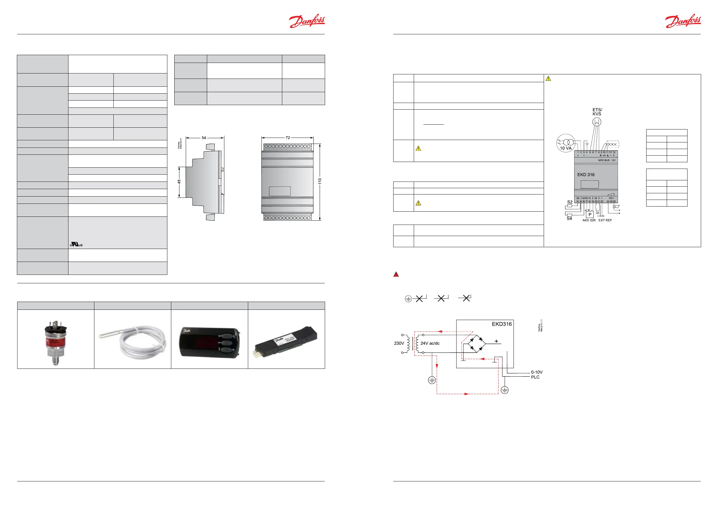
Necessary connections
Terminals:
1-2
Supply voltage 24 V a.c./d.c.
A dedicated transformer must be used.
3-4 Battery (the voltage will close the ETS valve if the
controller loses its supply voltage).
The battery voltage must not be connected from terminals 1
and 2.
Danfoss
24V 18V
Connections
ETS/KVS
White 5
Black 6
Red 7
Green 8
ETS 6/
Saginomiya valves
Orange 5
Yellow 6
Red 7
Black 8
5-8 Supply to stepper motor
9-13
Operation via data communication
EITHER EKA 164A OR System unit + software.
It is important that the installation of the data communication
cable be done correctly.
Cf. separate literature No. RC8AC...
20-21 Switch function for start/stop of regulation.
Note:
If a switch is not connected, terminals 20 and 21 must be short
circuited.
Application-dependent connections
Superheat control
14-15 Pt 1000 sensor at evaporator outlet (S2)
15-16 Pt 1000 sensor for measuring air temperature (S4)
17-19 Pressure transmitter type AKS 32R
Note:
The signal can not be shared with other controllers
Control of the valves opening degree with analog signal
21-22 Current signal or voltage signal from other regulation
(Ext. Ref.)
24-26 Alarm relay
There is connection between 24 and 26 in alarm situa tions.
Connections
Connection to earth will destroy the controller
1,2 3,4 21,22
Class II
Warning
Any external connection with grounding could create a ground
loop through a diode in the rectier bridge which could destroy
the power supply in EKD 316.
Data