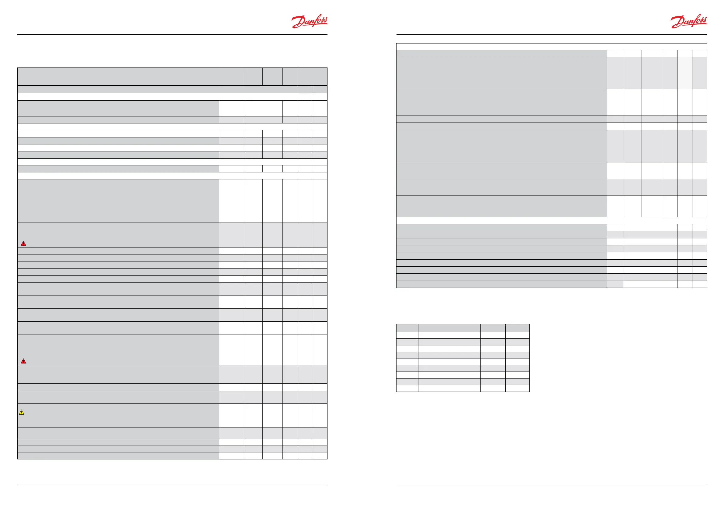
Menu survey
Function Parameter Min. Max.
Fac.
set-
ting
Application
choice
menu = o61
The menus from either column 1 or column 2 are shown 1 2
Normal display
During regulation the actual level of superheating is displayed.
(If you would like to see the expansion valve’s actual opening degree, press the bottom button for
approx. one second.)
- K -
During control with an analogue signal the opening degree is displayed. - % -
Reference
Units (0=°C+bar/1=°F+psig) r05 0 1 0
Correction of signal from S2 r09 -10.0 K 10.0 K 0.0
Correction of signal from S4 r10 -10.0 K 10.0 K 0.0
Start/stop of refrigeration r12 O/0 On/1 O/0
Alarm
Battery monitoring A34 O/0 On/1 O/0
Regulating parameters
Valve denition:
0 = ETS 12.5, ETS 25, KVS 15
1 = ETS 50, CCM 10, CCM 20, CCM 30
2 = ETS 100, CCM 40
3 = ETS 250, KVS 42
4 = ETS 400
5 = user-dened
6 = Saginomiya UKV/SKV/VKV/PKV
7 = ETS 6
8 = CCMT 2, CCMT 4, CCMT 8
n03 0 8 1
On using external display EEKA 164A, please check page 9 section ETS valve
P: Amplication factor Kp
o56 = 1; n04 = 2.0
o56 = 2; n04 = 0.7
(
Warning: Changes to n04 are lost when changing o56)
n04 0.5 20 2.0/0.7
I: Integration time T n05 30 s 600 s 120
D: Dierentiation time Td (0 = o ) n06 0 s 90 s 0
Max. value of superheat reference n09 2 K 15 K 10
Min. value of superheat reference n10 1 K 12 K 6
MOP (max = o) n11 0.0 bar 200 bar 20
Signal reliability during startup. Safety time period.
Should only be changed by trained sta
n15 0 sek. 90 sek 0
Signal reliability during startup – opening degree’s start value. Should only be changed by trained
sta.
n17 0% 100% 0
Stability factor for superheat control.
Changes should only be made by trained sta
n18 0 10 5
Damping of amplication around reference value
Changes should only be made by trained sta
n19 0.0 1.0 0.3
Amplication factor for superheat
Changes should only be made by trained sta
o56 = 1; n20 = 0.4
o56 = 2; n20 = 3.0
(
Warning: Changes to n20 are lost when changing o56)
n20 0.0 10.0 0.4/3.0
Denition of superheat control mode
1 = MSS,
2 = LOADAP
n21 1 2 1
Value of min. superheat reference for loads under 10% n22 1 K 15 K 4
Max. opening degree
Changes should only be made by trained sta
n32 0 % 100 % 100
Number of steps from 0-100% opening degree (only if n03 = 5 (User-dened))
Note: The display can only show three digits, but the setting value is four digits.
Only the three most important are shown, i.e. a reading of e.g. 250 means a setting of 2500. (Auto-
matic setting when valve is selected in n03).
n37
10
(100
stp)
990
(9990
stp)
262
Number of steps per second n38 5 stp/s
300
stp/s
300
Start backlash (extra closing steps at 0% opening (in % of n37)) n39 0% 100% 10
Integration time for inner loop (TnT0) n44 10 s 120 s 30
Compensation for spindle play n40 0 stp 100 stp 23 stp
SW = 1.32
Appendix I
©Danfoss A/S (AC-MCI / sw), 2014-03 DKRCC.PS.RP0.A1.02/520H7142 1716 DKRCC.PS.RP0.A1.02/520H7142 ©Danfoss A/S (AC-MCI / sw), 2014-03
Manual Superheat controller type EKD 316Manual Superheat controller type EKD 316
Conguration settings (n03, n37, n38, n39, n40, o03, o30, o56 and o61) available only when regulation is stopped (r12=o).
Factory settings are indicated for standard unit (see code number, page 1). Other code number have customised settings.
Miscellaneous
Controller’s address o03 0 240 240
If the valve’s opening degree should be controlled with an external signal, the signal is dened as:
0: no signal
1: 0-20 mA
2: 4-20 mA
3: 0-10 V
4: 1-5 V
o10 0 4 0
Manual control of outputs:
OFF: no manual control
1: Manual control with "o45" enabled
2: Simulate Alarm o : connection between 24 and 25
3: Simulate Alarm on : connection between 24 and 26
o18 o/0 3 O /0
Working range for pressure transmitter – min. value o20 -1 bar 0 bar -1.0
Working range for pressure transmitter – max. value o21 1 bar 200 bar 12.0
Refrigerant setting
o30 0 37 0
1 = R12
2 = R22
3 = R134a
4 = R502
5 = R717
6 = R13
7 = R13b1
8 = R23
9 = R500
10 = R503
11 = R114
12 = R142b
13 = User def.
14 = R32
15 = R227
16 = R401A
17 = R507
18 = R402A
19 = R404A
20 = R407C
21 = R407A
22 = R407B
23 = R410A
24 = R170
25 = R290
26 = R600
27 = R600a
28 = R744
29 = R1270
30 = R417A
31 = R422A
32 = R413A
33 = R422D
34 = 427A
35 = R438A
R36 =
Opteon XP10
37 = R407F
Manual control of the valve’s opening degree. The function can only be operated if o18 has been set to
"1".
This function is only for manual operation. It must not be used for as a regulation function.
o45 0 % 100 % 0
Selection of control mode:
1=Normal
2 = With inner loop (S media temperature less T0)
o56 1 2 1
Application mode. Menus blanked out so only the shaded menus are seen. See the two columns to the
right.
1: Controlling a valve with an analogue signal
2: Superheat regulation
o61 1 2 2 1 2
Service
Analog input (21-22) u06 mA (V)
Read status of input DI (20-21) u10 on/o
Temperature at S2 sensor u20 °C
Superheat u21 K
Superheat reference u22 K
Read valve’s opening degree u24 %
Read evaporating pressure u25 bar
Read evaporating temperature u26 °C
Temperature at S4 sensor u27 °C
Valve overview
n03 Valve type n37 n38
0 ETS 12½, ETS 25, KVS 15 262 300
1 ETS 50, CCM 10, CCM 20, CCM30 262 300
2 ETS 100, CCM 40 353 300
3 ETS 250, KVS 42 381 300
4 ETS 400 381 300
5 -
6 Saginomiya 24 30
7 ETS 6 24 30
8 CCMT 2, CCMT 4, CCMT 8 110 300