Do you have a question about the Danfoss EVR 2 and is the answer not in the manual?
Details on Solenoid Valve types EVR 2-22 NC/NO and compatible refrigerants.
Instructions for valve mounting directions, soldering, and flare mounting.
Guidance on coil installation, O-ring placement, and electrical connections.
Procedures for mounting and dismounting the valve's top part and seat.
This document describes the installation and maintenance of Danfoss Solenoid Valves, specifically types EVR 2 – 22, available in Normally Closed (NC) and Normally Open (NO) configurations. These valves are designed for use with a range of refrigerants, including R22/R407C, R404A/R507, R410A, R134a, R407A, and R23. For applications involving other refrigerants, users are advised to contact Danfoss directly.
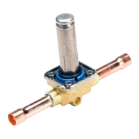
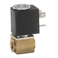
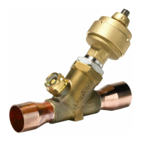
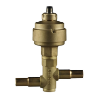
The solenoids are depicted in various configurations: EVR (NC flare), EVR (NC solder), EVR (NC flange), and EVR (NO solder). These different connection types offer flexibility for integration into various refrigeration systems.
The manual provides clear instructions for mounting the solenoid valves. For EVR (NC flare), EVR (NC solder), and EVR (NC flange) types, the mounting directions are illustrated, indicating a 90-degree rotation. The EVR (NO solder) type also shows its specific mounting orientation.
A critical aspect of installation is the correct assembly of the coil and O-ring. The diagram highlights the importance of ensuring the O-ring is properly seated. For UL-certified products, a sticker indicates compliance. A crucial safety warning is provided: never switch on power to the coil when it is dismounted from the valve. Doing so can damage the coil and poses a risk of injury and burns to the user.
The electrical connections are illustrated, showing the wiring setup for the solenoid valve. The maximum coil temperatures are specified for different coil wattages (9 W a.c. for EVR 2, 10/12 W a.c., 20 W d.c., and 10 W a.c.), ranging from 40 °C (105 °F) to 80 °C (175 °F). The media temperature range is also provided, from a minimum of -40 °C (-40 °F) to a maximum of 105 °C (221 °F).
For solder connections, the maximum soldering temperature is 700 °C (1300 °F), with the maximum temperature at the valve body limited to 100 °C (212 °F). This ensures that the valve's internal components are not damaged during the soldering process. Flare mounting is also depicted, illustrating the proper technique for securing the valve.
Instructions for mounting and dismounting the coil are provided, showing the "On" and "Off" positions, which likely correspond to the energized and de-energized states or the physical attachment/removal of the coil.
Detailed steps are given for mounting and dismounting the top part of the valve. This involves specific torque values for different EVR types, ensuring proper sealing and operation. For EVR 2 and EVR 3, the torque is 1.4 Nm (0.15 kpm, 1 ft-lbs) with a T15 Torx size. For EVR 4, EVR 6, and EVR 8, the torque is 2.0 Nm (0.2 kpm, 1.44 ft-lbs) with a T15/T20 Torx size. Larger valves like EVR 10, EVR 15, and EVR 18 require 2.8 Nm (0.3 kpm, 2 ft-lbs) with a T25 Torx, while EVR 20 and EVR 22 require 12 Nm (1.2 kpm, 9 ft-lbs) with a T40 Torx.
The manual illustrates the correct placement of the valve seat, a crucial component for proper valve function. For EVR 4-8, specific instructions are given for dismounting the gasket and supporting ring: "Press and twist."
The document provides exploded views and assembly diagrams for various valve configurations:
For many of these configurations, a "Sticker applies only to UL products" note is present, indicating specific requirements or certifications for valves intended for the UL market. These detailed diagrams are essential for proper assembly, disassembly, and maintenance, ensuring that all components are correctly installed and torqued to prevent leaks and ensure optimal performance. The emphasis on specific torque values and O-ring placement underscores the precision required for reliable operation of these solenoid valves in refrigeration systems.
| Housing Material | Plastic |
|---|---|
| Valve Type | Solenoid Valve |
| Power Supply | 24 V AC/DC |
| Control Signal | PWM (Pulse Width Modulation) |
| Storage Temperature | -20°C to +70°C |
| Weight | 0.2 kg |