EasyManuals Logo

Danfoss iC7 Series Installation Guide

Danfoss iC7 Series
18 pages
To Next Page IconTo Next Page
To Previous Page IconTo Previous Page
Page #17 background imageLoading...
Page #17 background image
2.
3.
4.
5.
6.
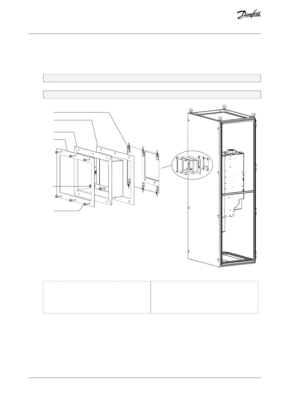
Seat the clip-on nuts into the 6 holes around the opening.
Affix 2 back vent gaskets to the flange of the back vent, placing 1 gasket on the inner side and 1 gasket on the outer side of
the flange.
Slide the back vent into the opening in the back plate.
Fasten the M6x12 screws around the inner edge of the back vent.
The FA09 kit requires 6 screws, and the FA10 kit requires 8 screws.
Secure the M5x18 screws in the flange of the back vent, attaching the vent to the back plate.
The FA09 kit requires 6 screws, and the FA10 kit requires 8 screws.
1
2
3
4
5
6
e30bj237.10
Illustration 14: Installation of Back Vent
1
Clip-on nut
2
Back vent gasket (inner)
3
Back vent
4
Back vent gasket (outer)
5
M6x12 screw
6
M5x18 screw
AN371942757356en-000101 / 136R0252 | 17Danfoss A/S © 2022.03
Installation
In-bottom/Out-back Cooling Kit for FA09-FA10
Installation Guide

Other manuals for Danfoss iC7 Series

Questions and Answers:

Question and Answer IconNeed help?

Do you have a question about the Danfoss iC7 Series and is the answer not in the manual?

Danfoss iC7 Series Specifications

General IconGeneral
Product TypeMedia Converter
Power Supply24 VDC
Housing MaterialPlastic
MountingDIN Rail
ManufacturerDanfoss
Protection ClassIP20
Protocols SupportedModbus
Humidity5% to 95% (non-condensing)
Weight150 g
SeriesiC7 Series

Related product manuals