© Danfoss | DCS (MWA) | 2016.12
DKRCI.PI.HS1.A6.ML | 520H6354 | 4
ENGLISH
Installation
Refrigerants
Applicable to HCFC, HFC, R717(Ammonia)
and R744 (CO
2
).
Flammable hydrocarbons are not
recommended.
The valve is only recommended for use in
closed circuits. For further information please
contact Danfoss.
Please note:
The ICLX function modules can only
be used in housings
produced in or after week 49 2012;
thus the week code on the housing
must be 4912 or higher.
Temperature range
–60/+120°C (–76/+248°F)
Pressure
The valves are designed for a max.
working pressure of 52 bar g (754 psi g).
Application
The ICLX is used in suction lines for the
opening against high dierential pressure,
e.g. after hot gas defrost in large industrial
refrigeration systems with ammonia,
ourinated refrigerants or CO
2
.
The ICLX opens in two steps:
Step one opens to approx. 10% of the
capacity, when the pilot solenoid valves are
activated.
Step two opens automatically after the
pressure dierential across the valve reaches
approximately 1 bar.
External pressure
The external pressure applied to the ICLX
should always be 1.5 bar higher than the inlet
pressure of the valve. This will give the valve a
MOPD of 28 bar. If the external pressure is
2 bar higher than the inlet pressure the MOPD
of the ICLX will be 40 bar.
Electrical wiring
The ICLX valve is a normally closed design.
To ensure that the valve operates as normally
closed it is important that the EVM NC pilot is
mounted in the pilot port next to the external
pressure inlet (g. 2). For normal operation
mode both pilots should be energized
simultaneously, e.g. same signal can be used
for both pilots.
Coil requirements
Both coils must be IP67.
EVM NC: 10W ac (or higher) for MOPD
up to 21 bar
EVM NC: 20W ac for MOPD 21 → 40 bar
EVM NO: 10W ac (or higher)
The valve will have a malfunction
in systems where the pressure
dierential across the valve in normal
open conditions will exceed 1 bar (15
psig). In this case the step two of the
valve will close.
Orientation
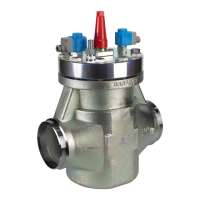
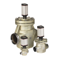
The valve must be installed with the arrow in
the direction of the ow and with the pilots
pointing in one of the directions shown in
g.1. Downwards pointing pilots (any angle)
is not possible. The top cover can be rotated 4
X 90° in relation to the valve body.
If the ICLX is installed with a vertical pilot
orientation (see g. 1) attention should be
paid to have the EVM NO in lower position. If
needed rotate the top cover.
The valve is tted with a spindle for manual
opening. Make sure that the external pilot
line is connected to the upper side of the
main line so that any dirt and oil from the
plant will not nd its way into the pilot line.
The valve is designed to withstand a high
internal pressure. However, the piping system
should be designed to avoid liquid traps and
reduce the risk of hydraulic pressure caused
by thermal expansion. It must be ensured
that the valve is protected from pressure
transients like “liquid hammer” in the system.
Welding (g. 5 and 8a)
The top cover (g. 8a, pos. 2) and function
module (g. 8a, pos. 3), must be removed
before welding to prevent damage to o-rings
and teon (PTFE) in the function module.
Often the cover and function module can be
removed while still assembled (g. 3a), but if
the internal O-rings stick to the metal surface
it is necessary to disassemble in 2 steps
(g. 3b). In both cases the parts can be lifted
out by the careful use of 2 screwdrivers.
Note: Remove all parts from the valve body
before welding (as shown in g. 5).
The internal surfaces and weld
connections of the enclosed ICLX
valve have been applied with
an anti-corrosion treatment.
In order to maintain the eectiveness
of this anti-corrosion treatment, it is
important to ensure that the valve is
disassembled just prior to the welding
process being undertaken.
In the event that the function modules are
to be left disassembled for even a short
period, please ensure that the function
modules are further protected by placing
in a polyethylene bag or by applying a rust
protection agent (e.g. refrigeration oil or
BRANOROL) on the surfaces.
Only materials and welding methods,
compatible with the valve body material,
must be applied to the valve body.
Avoid welding debris and dirt in the
valve body and the function module. The
valve body must be free from stresses
(external loads) after installation.
The valves must not be mounted in systems
where the outlet side of the valve is open
to atmosphere. The outlet side of the valve
must always be connected to the system
or properly capped o, for example with a
welded-on end plate.
Assembly
Remove welding debris and any dirt from
pipes and valve body before assembly. Check
that the o-rings are intact before replacing
the function module. If possible, apply some
refrigeration oil to ease the insertion and to
protect the o-rings. Check that the top gasket
has not been damaged. If the surface has
been damaged or the gasket has been bent, it
must be replaced.
Tightening (g. 6)
Tighten the top cover with a torque wrench,
to the values indicated in the table.
Colours and identication
The ICLX valves are Zinc-Chromated from
factory. The Zinc-Chromatization does not
cover the welding connections.
If further corrosion protection is required, the
valves can be painted.
The external surface of the valve housing
must be protected against corrosion with
a suitable top coating after installation
involving welding and consequent assembly.
Protection of the ID plate when painting the
valve is recommended.
Important note for ICLX valves:
The ICLX valve is kept in its open
position by hot gas. The hot gas
condenses in the cold valve and
creates liquid under the servo piston.
When the pilot valves change status to close
the ICLX, the pressure on the servo piston
equalises with the suction pressure through
the pilot valve.
This equalisation takes time because
condensed liquid is present in the valve.
The exact time taken from when the pilot
valves change position to complete closing
of the ICLX will depend on temperature,
pressure, refrigerant and size of valve. Thus
an exact closing time for the valves cannot
be given but, in general, lower temperatures
give longer closing times.
It is very important to take the closing times
into consideration when hot gas defrost is
performed on evaporators.
Steps must be taken to ensure that the
hot gas supply valve is not opened before
the ICLX in the suction line is completely
closed. If the hot gas supply valve is opened
before the ICLX in the suction line is closed,
considerable energy will be lost and
potentially dangerous situations might arise
because of “liquid hammer”. In ICLX valves,
the spring-loaded second stage might be
induced to hammer by gas and liquid being
forced through the valve at Δp > 1.5 bar
across the ICLX. The nal result could be
severe damage to the valve.
As a rule of thumb a closing time of 2
minutes can be used as a starting point.
The optimum closing time for each
individual system must be determined
at initial start-up of the plant at intended
operational conditions. It is recommended
to check if the closing time needs to be
changed when conditions changes (suction
pressure, ambient temp. etc.) and closing
time should be checked at service of the
valve.
Once the optimum closing time has been
identied it is recommended to add a safety
margin of 30 sec. to the optimum closing
time.
Maintenance
Service
The ICLX valves can be disassembled for
service purposes.
Only skilled and trained refrigeration
engineers are allowed to service the ICLX
valves.
Do not open the valve while the valve is still
under pressure.
Pressure relief can be done by carefully
opening the manual operating spindle. Small
grooves along the thread will release
refrigerant into open air. This operation must
only be done after providing the correct
countermeasures under local legislation.
 Loading...