Do you have a question about the Danfoss MAGFLO MAG 1100 and is the answer not in the manual?
Overview of MAGFLO® electromagnetic flowmeters, their applications, and key features like SENSORPROM® memory.
Explains the working principle based on Faraday's law, detailing sensor and signal converter functions and components.
Detailed specifications for MAG 1100 Ceramic, PFA, and MAG 1100 Ex sensor types, including pressure, temperature, and materials.
Technical specifications for the MAG 1100 FOOD sensor, covering hygienic adapters, temperature, and enclosure ratings.
Specifications for MAG 3100 series sensors with flanges, detailing medium temperature, liners, and operating pressure.
Specifications for the MAG 5100 W sensor, including design, liner, temperature, and flange options.
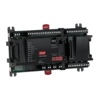
Technical details for the MAG 5000 signal converter, covering outputs, digital inputs, power supply, and approvals.
Specifications for the MAG 6000 signal converter, including current/digital outputs, communication, and power supply options.
Details on safety barriers used with MAG 6000 and MAG 1100 Ex/3100 Ex sensors for hazardous areas.
Specifications for the cleaning unit used with MAG 5000 and MAG 6000 rack mount systems to clean electrodes.
Details on meter uncertainty for MAG 5000/6000 converters with MAG 3100 W/MAG 1100 PFA or MAG 3100/MAG 1100 Ceramic/MAG 5100 W sensors.
Illustrates output characteristics for 0-20 mA, 4-20 mA, frequency, pulse output, relay, limit switch, and batch outputs.
Information on sensor cable requirements and the impact of medium conductivity on measurement accuracy.
Specifies minimum data requirements for cables used with MAGFLO® flowmeters, including resistance and capacitance.
Details about the HART® communication standard and modes for MAG 5000/6000 converters.
Specifications for standard and special cables supplied by Danfoss, including shielding and ambient temperature ratings.
Provides a sizing table relating flow velocity, flow quantity, and sensor dimension size for flowmeter selection.
Specifies minimum conductivity requirements for different installation types and applications.
Guides the selection of appropriate liner materials for various applications and media types.
Recommends electrode materials based on application requirements, chemical resistance, and media properties.
Provides guidelines for optimal installation of sensors, including orientation, pipe sections, and avoiding air bubbles.
Explains the theory of operation for the cleaning unit, including AC and DC cleaning methods for electrode deposits.
Information regarding custody transfer approval, including sealing and internal counter usage for billing.
Describes the procedure for sealing signal converters approved for custody transfer applications.
Details on Ex-installations, including safety barrier usage, sensor approvals, and marking definitions for hazardous areas.
Provides dimensional data and weight information for the MAG 1100 sensor, including tables for different sizes and gasket options.
Presents dimensions and weight for the MAG 1100 FOOD sensor, including built-in length variations.
Details dimensions and specifications for accessories like weld-in and clamp adapters for the MAG 1100 FOOD sensor.
Presents detailed dimensions for the MAG 5100 W sensor across various nominal sizes and flange standards.
Provides dimensional data and weight for MAG 3100 and MAG 3100 W sensors, covering various flange types and sizes.
Details dimensions and weights for different signal converter mounting types: integral, wall mount, and rack mount units.
Explains the importance of potential equalization and methods for achieving it with different piping and gasket types.
Covers inlet protection requirements for MAG 3100 sensors, especially with abrasive liquids, using grounding rings.
Provides special attention notes for systems with cathodic protection, covering integral and remote installation grounding.
Step-by-step instructions for integral mounting of MAG 5000 and MAG 6000 signal converters onto sensor terminal boxes.
Instructions for remote sensor end installation, including SENSORPROM® unit transfer and cable connections.
Detailed steps for wall mounting signal converters, including mounting brackets and pipe attachments.
Guidance for installing signal converters in rack systems, including mounting SENSORPROM®, guide rails, and connection boards.
Instructions for mounting signal converters using a wall mounting kit, including enclosure and SENSORPROM® unit placement.
Steps for installing signal converters via a front panel mounting kit, including enclosure fitting and cable connection.
Procedure for installing signal converters using a back of panel mounting kit, covering enclosure and connection board mounting.
Instructions for installing signal converters with safety barriers in rack systems, including SENSORPROM® unit and guide rail mounting.
Guidance for installing signal converters with cleaning units in rack systems, including SENSORPROM® unit and mode selection.
Provides a detailed connection diagram for MAG 5000/6000 signal converters, showing power supply, outputs, and sensor connections.
Illustrates wiring diagrams for integral and remote wall mount installations, including cable connections and grounding.
Explains the function of keypad keys and the layout of the alphanumeric display for flowmeter programming and operation.
Describes the menu structure, operator menu, and setup menu, including access modes and password protection.
Provides a menu overview map for MAG 5000 and MAG 6000 signal converters, detailing operator and setup menu navigation.
Presents the menu overview for the MAG 6000 CT signal converter, outlining navigation for operator and setup menus.
Details basic settings for the signal converter, including main frequency, flow direction, Qmax, totalizers, and error level configuration.
Explains the configuration of current, digital, and relay outputs for flow rate, pulse, frequency, and error signaling.
Details the setup for digital and relay outputs, including error level, error number, and direction/limit configurations.
Describes the functionality and configuration of the relay output, particularly for operating cleaning units.
Explains the configuration of external inputs for functions like batch control, totalizer reset, and forced outputs.
Details how to configure sensor characteristics, including SENSORPROM® status, sensor size, calibration, and excitation frequency.
Provides instructions for resetting totalizers, batch cycle counters, and default settings, including factory password reset.
Explains the service mode for accessing advanced settings like current/digital outputs, relay output, and error logging.
Guides the setup of operator menu display lines, allowing customization of displayed information like flow rate and totalizers.
Details how to view product identity information, including converter and sensor type, serial numbers, and software versions.
Instructions on how to change the operator password, including procedures for resetting it to the factory default.
Explains how to select the display language for the flowmeter interface from a list of available languages.
Covers HART® communication configuration, including short address, tag name, description, and software version.
Describes how to configure the operator menu to display flow rate and totalizer values on the primary display line.
Explains how to reset totalizers, including specific procedures for hot/cold water and other liquids based on approval types.
Details batch control operations, including starting, pausing, stopping, and resetting the batch cycle counter.
Lists factory default settings and available options for parameters like password, flow direction, outputs, and sensor characteristics.
Provides Qmax. values dependent on sensor dimensions for MAG 5100 W and MAG 1100/3100 series.
Lists batch and pulse output settings that are dependent on the sensor's dimension.
Explains settings specific to MAG 6000 CT, including blocking of primary parameters during normal operation and totalizer reset options.
Describes the error system, including error pending, status log, acceptance levels, and how errors are displayed and remedied.
Provides a comprehensive list of error numbers, their corresponding texts, comments, and recommended remedies.
A troubleshooting checklist to diagnose issues with MAGFLO® converters, covering power, connections, and output readings.
A table listing common symptoms, causes, and remedies for troubleshooting MAG 5000 and MAG 6000 flowmeters.
Provides a checklist for inspecting MAG sensors, including coil resistance, insulation, and electrode circuit checks.
Lists coil resistance values for MAG 3100 and MAG 5100 W sensors across various sizes and flange types.
Part numbers and descriptions for ordering MAG 1100 sensors, including Ceramic, PFA, High Temperature, Ex, and FOOD versions.
Part numbers for accessories related to MAG 1100 FOOD, such as gaskets, adapters, and grounding rings.
Part numbers for ordering MAG 3100 and MAG 3100 Ex sensors, covering nominal sizes, liner materials, flanges, and electrode types.
Part numbers for ordering MAG 3100 W sensors, specifying ANSI/AWWA and DIN flange types with different liner materials.
Part numbers for ordering MAG 5100 W sensors, detailing factory set Qmax., size, and flange types.
Part numbers for ordering MAG 5000 and MAG 6000 signal converters, including blind, standard, and CT versions with various enclosures.
Part numbers for MAG 5000 and MAG 6000 signal converters designed for rack and panel mounting, including inserts and accessories.
Part numbers for various accessories, including cables, cable entries, sealing screws, terminal boxes, and SENSORPROM® units.
Information on calibration options, including initial and re-calibration services, matched pairs, and accredited calibration procedures.
| Brand | Danfoss |
|---|---|
| Model | MAGFLO MAG 1100 |
| Category | Measuring Instruments |
| Language | English |