Do you have a question about the Danfoss MAGFLO MAG 6000 and is the answer not in the manual?
Explains the principle of electromagnetic flow measurement based on Faraday's law.
Detailed specifications for MAG 1100 and MAG 1100 Ex sensors.
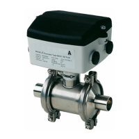
Detailed specifications for MAG 1100 FOOD sensor, including hygienic features.
Specifications for MAG 3100, MAG 3100 Ex, and MAG 3100 W sensors.
Continued specifications for MAG 3100, MAG 3100 Ex, and MAG 3100 W sensors.
Detailed specifications for MAG 5100 W sensor and MAG 5000/5000 CT.
Specifications for the MAG 5000 signal converter, covering various parameters and approvals.
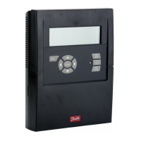
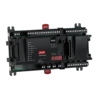
Specifications for the MAG 6000 signal converter, including communication and power options.
Technical details for safety barriers (ia/ib) used with specific MAGFLO® sensor sizes.
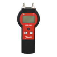
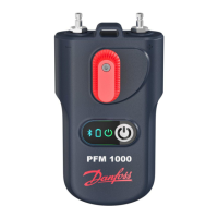
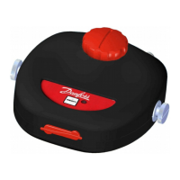
Information on the cleaning unit for MAGFLO® sensors and its application.
Details on meter uncertainty and how it is affected by operating conditions.
Overview of output characteristics for MAG 5000 and MAG 6000 in different modes.
Guidance on sensor cables and the impact of medium conductivity on performance.
Sizing table relating flow velocity, quantity, and sensor dimension.
Minimum conductivity requirements for different installation types.
Guide for selecting the appropriate liner material based on application.
Guide for selecting the appropriate electrode material based on application.
General conditions and considerations for installing the flowmeter.
Further guidance on installation conditions, including pipe orientation and flow direction.
Explanation of potential equalization methods for accurate measurement.
Recommendations for the direct burial of specific MAGFLO® sensor models.
Explanation of the cleaning unit's operation and its use for electrode maintenance.
Guidelines for installing MAGFLO® equipment in Ex hazardous areas.
Configuration of basic settings such as main frequency, flow direction, Qmax, and error level.
Configuration of current output and digital output settings (pulse/volume, frequency).
Configuration of digital output, relay output, error level, and error number.
Configuration and verification of sensor characteristics, including SENSORPROM® data.
Procedures for resetting totalizers, batch counters, and default settings.
Accessing and performing operations within the service mode for diagnostics and maintenance.
Customizing the operator menu display lines for flow rate, totalizers, and other parameters.
Overview of factory default settings and available parameter options for the signal converter.
Understanding the error system, error pending, status log, and error outputs.
A comprehensive list of error codes, their text, comments, and recommended remedies.
A checklist for diagnosing and troubleshooting MAGFLO® converter malfunctions.
Troubleshooting guide for common symptoms, causes, and remedies for MAG 5000 and MAG 6000.
Procedure for checking MAG sensors for defects, including resistance and insulation tests.
Information on initial and re-calibration services, including matched pairs and witness inspections.
| Brand | Danfoss |
|---|---|
| Model | MAGFLO MAG 6000 |
| Category | Measuring Instruments |
| Language | English |