Do you have a question about the Danfoss SONOMETER 1100 and is the answer not in the manual?
Warning about the energy meter's seal; damage invalidates warranty and verification.
Details on medium, temperature range, and operating/ambient conditions.
Details on pipe placement, flow direction, sensor orientation, and system pressure.
Guidance on placement away from interference, accessibility, and isolation valves.
Procedure for separating the calculator in high temperature or cooling applications.
Guides sensor cable identification, handling, symmetrical mounting, and immersion requirements.
Details on installing sensors in pockets and ball valves/adapters, including pocket orientation and sealing.
Crucial warning that improper installation invalidates warranty and verification.
Details the two power source options: long-life lithium battery or mains unit supply.
Information on battery type, handling, charging prohibition, temperature impact, and disposal.
Guidance on connecting mains units, fusing, safety cover, and phase connection warning.
Explains the role of the backup battery during mains power failure.
Instruction to seal components and put the meter into operation after installation.
Procedure for bleeding the system and verifying flow and temperature readings on the display.
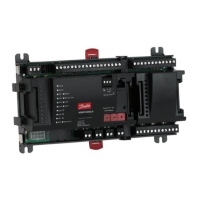
Overview of available expansion modules, slot usage, and compatibility rules.
Mandatory observance of ESD regulations to prevent damage to electronic circuits.
Step-by-step guide for opening the calculator, inserting modules, connecting cables, and closing.
Details on integrated radio module specifications for OMS communication.
Information on the M-Bus module for serial communication with control centers.
Description of RS232 and RS485 modules for PC communication, including wiring.
Details on pulse input module for additional meters, programming, and units.
Information on pulse output module for data transmission with specifications.
Description of the combined input/output module for flow sensors.
Details on analogue output module for passive connections and current loops.
Overview of display loops and windows for system information display.
Details on standard display windows for energy, volume, flow, and temperatures.
Information on accounting date loops, error hours, and system information displays.
Details on pulse input values and monthly value displays for tariff meters.
Explanation of how to use the push-button to navigate through displays and loops.
List of common error codes, their descriptions, and potential causes.
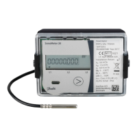
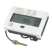
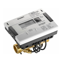
The Danfoss SONOMETER™ 1100 is an ultrasonic compact energy meter designed for accurate measurement in various heating and cooling applications. This device is engineered for reliable performance and ease of integration into existing systems, providing essential data for energy management and billing.
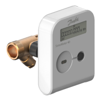
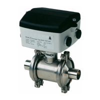
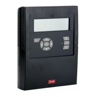
The SONOMETER™ 1100 operates on ultrasonic principles to measure energy consumption. It consists of a calculator, a volume measuring component (flow sensor), and two temperature sensors. The flow sensor is installed in either the forward or return pipe, depending on the application (heat or cooling meter), and measures the volume of the medium flowing through the system. The temperature sensors, one for the hot line (TH) and one for the cold line (TC), measure the inlet and outlet temperatures. The calculator then processes these measurements to determine the energy consumed or supplied.
The meter supports various communication channels, including an integrated radio module for wireless communication and wired communication modules such as M-Bus, RS232, and RS485. These modules allow the meter to transmit data to external control centers or reading devices, facilitating remote monitoring and data collection. The radio communication is unidirectional, sending data at regular intervals, and adheres to "Open Metering" or "DM Standard" protocols, with data encryption for security.
Expansion modules enhance the meter's functionality. It features two slots for these modules, which can be combined to meet specific requirements. Available modules include pulse input for additional meters, pulse output for transmitting consumption data, combined input/output modules, and analogue output modules (4-20mA) for integrating with building management systems. These modules allow for flexible system configurations and data integration.
The meter's display provides comprehensive information through various "loops" or windows, which can be navigated using a push-button. These displays show accumulated energy, volume, flow rate, temperatures, operating days, error status, accounting dates, and module information. The display is designed for user-friendliness, with numbered loops to help users quickly find the desired data.
The SONOMETER™ 1100 is designed for straightforward installation and operation. It can be powered by a lithium battery, offering long lifetimes (11 or 16 years), or by a 230V AC / 24V AC mains unit. The choice of power supply allows for flexibility depending on site requirements. In case of mains power failure, a backup battery ensures that LCD readings, date, and time remain updated, though measuring functions and radio communication may be reduced to conserve power.
Installation of the flow sensor requires careful attention to the direction of flow, aligning with the arrow on the sensor. While calming sections are not strictly necessary, 3xDN sections are recommended before the meter for optimal performance. The meter can be installed in both horizontal and vertical pipe sections, ensuring that air bubbles do not collect within the meter. For applications with medium temperatures above 90°C or where condensation is expected, the calculator should be removed from the meter and installed at a distance using a wall holder or space holder.
Temperature sensors must be handled carefully and mounted symmetrically, either directly immersed or in pockets. The sensor cables are color-coded (red for hot line, blue for cold line) for easy identification and correct connection to the terminals. After installation, the temperature sensors must be sealed to ensure accuracy and prevent tampering.
The meter's push-button allows for simple navigation through the display loops. A short press switches to the next display within a loop, while a long press switches to the next display loop. The display automatically switches off after approximately 4 minutes of inactivity to save power, returning to the basic "Energy" window when the button is pressed again.
Maintenance of the SONOMETER™ 1100 is designed to be minimal but requires adherence to specific guidelines to ensure accuracy and validity of the warranty. The energy meter must be sealed after installation, and any damage to these seals will invalidate the factory warranty and verification. This emphasizes the importance of professional installation and careful handling.
The device includes an error code display in the main loop, which automatically appears if an error occurs. These error codes provide valuable diagnostic information, such as temperature range issues, sensor interchange, hardware errors, communication problems, incorrect flow direction, or battery status. Errors present for longer than 6 minutes are saved in an error log, aiding in troubleshooting and historical analysis. The error display disappears automatically once the cause of the error has been cleared.
Used batteries must be disposed of at suitable waste collection points, and replacing the battery with an incorrect type carries a risk of explosion. When installing expansion modules, relevant ESD (electrostatic discharge) regulations must be observed to prevent damage to electronic circuits. The modules can be fitted retrospectively without damaging the verification mark, offering flexibility for upgrades or changes in functionality.
For systems with mains power, a protective safety cover must be installed at all times. It is crucial not to connect between the two phases of the power supply unit, as this will destroy the unit. The cables supplied with the meter must not be shortened, extended, or changed in any other way to maintain system integrity and warranty. Regular checks of the flow rate and temperatures displayed are recommended during start-up operation to ensure plausible indications and proper system bleeding.
| Type | Ultrasonic Flow Meter |
|---|---|
| Pressure range | Up to 25 bar |
| Protection class | IP65 |
| Accuracy | Class 2 |
| Communication | M-Bus, Modbus, BACnet |
| Measurement Principle | Ultrasonic transit time |
| Outputs | Pulse |
| Operating Temperature | -20°C to +60°C |
| Storage Temperature | -25°C to 70°C |
| Housing Material | Stainless steel |