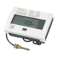
Instruction SONOMETER™ 1100
8.5 Pulse input function module
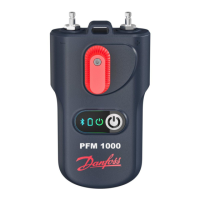
Module for two additional meters. Pulse input 1 is marked as “I1- ”,
input 2 with “I2 - “. Pulse inputs can be programmed (IZAR@SET) with
a value: 1, 2.5, 10, 25, 100, 250, 1000, 2500 litre per pulse.
• Pulse transmitter must be electrically isolated, e.g. Reed contact
• Possible units are all the energy units available in the meter, the
volume unit m³ or no unit.
Data is accumulated separately in registers; can be read in the dis-
play as IN1 and IN2 and can be transferred via the communication
modules.
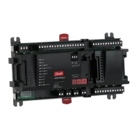
8.6 Pulse output function module
The module is equipped with 2 pulse outputs, which can be freely
programmed using the IZAR@SET software. The outputs are marked
as “O1 - “ and “O2 - “ on the terminal strip and as Out1 and Out2
on the display.
• External supply: Vcc = 3-30 VDC
• Output current ≤ 20 mA with a residual voltage of ≤ 0.5 V
• Open Collector (Drain)
• Electrically isolated
• Output 1: f ≤ 4 Hz Pulse duration: 125 ms ±10 %
Pulse pause: ≥ 125 ms –10 %
• Output 2: f ≤ 100 Hz Pulse duration pulse/pause ~1:1
• The volume pulse rate can be freely programmed
• Standard: last digit in the display
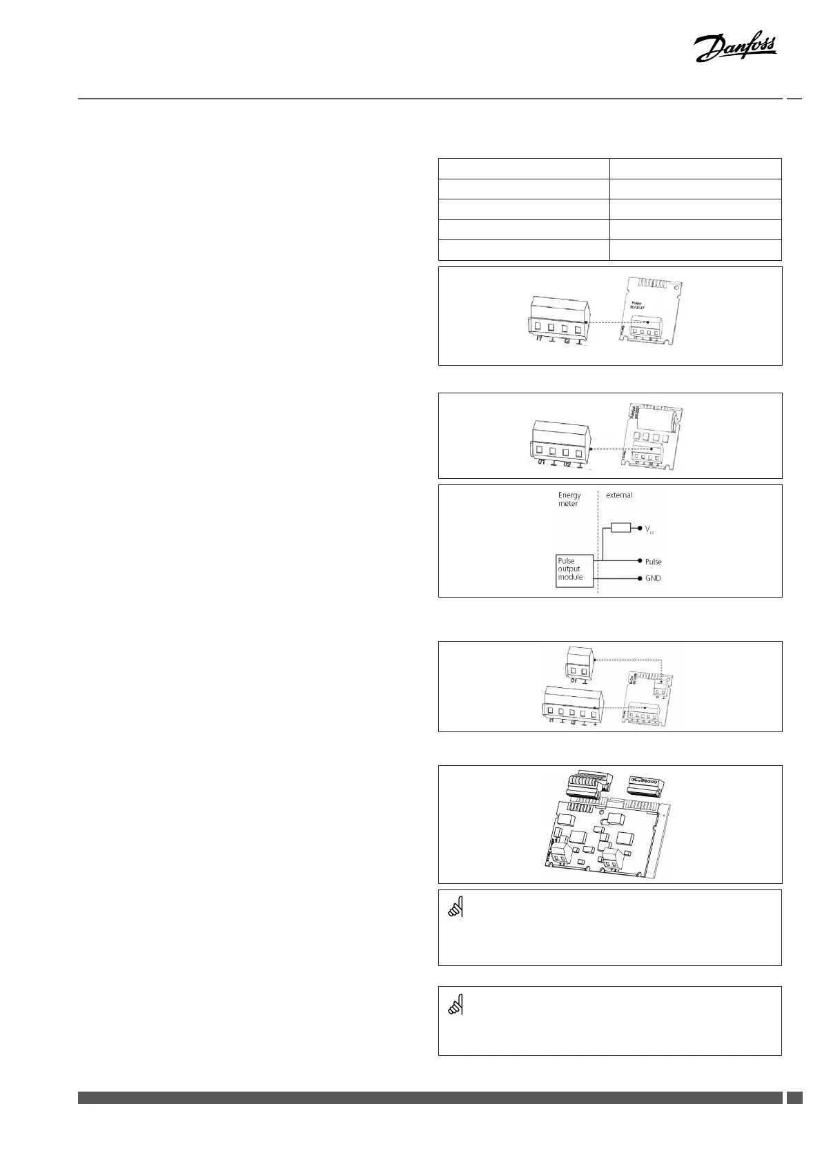
8.7 Combined function module (IN/OUT)
The combined module has 2 inputs and 1 output.
See chapter 8.5 for the specic characteristics on the pulse input.
A 3 VDC voltage is connected to the “+” terminal and can be used as
the supply for a ow sensor.
The pulse output has the same characteristics as pulse output 1 speci-
ed under 8.6. It is not, however, electrically isolated.
8.8 Analogue output function module
The module has 2 passive analogue output connections which are
freely programmable using the IZAR@SET software. On the terminal
strip, the electrically isolated outputs “1” and “2” are marked and the
polarity is indicated (“+” and “–”).
• Passive, external power supply: 10…30 VDC
• Current loop 4 … 20 mA whereat 4 mA = 0 value;
20 mA = programmable maximum value
• Overload up to 20.5 mA, then residual current
• The module displays errors with 3.5 mA or 22.6 mA
(programmable)
• Output values: power, ow, temperatures
8.9 Test output
The internally located test output is intended for testing
laboratories. The manufacturer supplies two special cables:
1. Volume testing pulse
2. Energy testing pulse
Please refer to the inspection and testing manual for further
specications (pulse rate, pulse duration/pause, pulse frequency).
Input frequency ≤ 8 Hz
Min. pulse duration 10 ms
Input resistance 2.2 M
Terminal voltage 3 VDC
Cable length up to 10 m
The module is connected with the meter electronics by means of
a ribbon cable. The separate plug connector on module slot 2 is
necessary for the perfect functioning of the analogue outputs.
Ensure that the temperature sensors (measurement resistances)
remain in contact without interruption during energy verication.
T
T
T T
Danfoss District Energy VI.SH.K1.02 DEN-SMT/PL
7