20-20 Feedback Function
Option: Function:
[6] Multi
Setpoint
Max
Sets up the PID Controller to calculate the
difference between Feedback 1 and Setpoint 1,
Feedback 2 and Setpoint 2, and Feedback 3 and
Setpoint 3. It uses the feedback/setpoint pair in
which the feedback is farthest above its
corresponding setpoint reference. If all feedback
signals are below their corresponding setpoints,
the PID Controller uses the feedback/setpoint
pair in which the difference between the
feedback and the setpoint reference is the least.
NOTICE
If only 2 feedback signals are used, the
feedback that is not to be used must be
set to [0] No Function in
parameter 20-00 Feedback 1 Source,
parameter 20-03 Feedback 2 Source or
parameter 20-06 Feedback 3 Source. Note
that each setpoint reference will be the
sum of its respective parameter value
(parameter 20-21 Setpoint 1,
parameter 20-22 Setpoint 2 and
20-23 Setpoint 3) and any other references
that are enabled (see parameter group
3-1* References).
NOTICE
Any unused feedback must be set to [0] No function in
its Feedback Source parameter:
Parameter 20-00 Feedback 1 Source,
parameter 20-03 Feedback 2 Source or
parameter 20-06 Feedback 3 Source.
The feedback resulting from the function selected in
parameter 20-20 Feedback Function is used by the PID
Controller to control the output frequency of the
frequency converter. This feedback can also be shown on
the frequency converter’s display, be used to control a
frequency converter's analog output, and be transmitted
over various serial communication protocols.
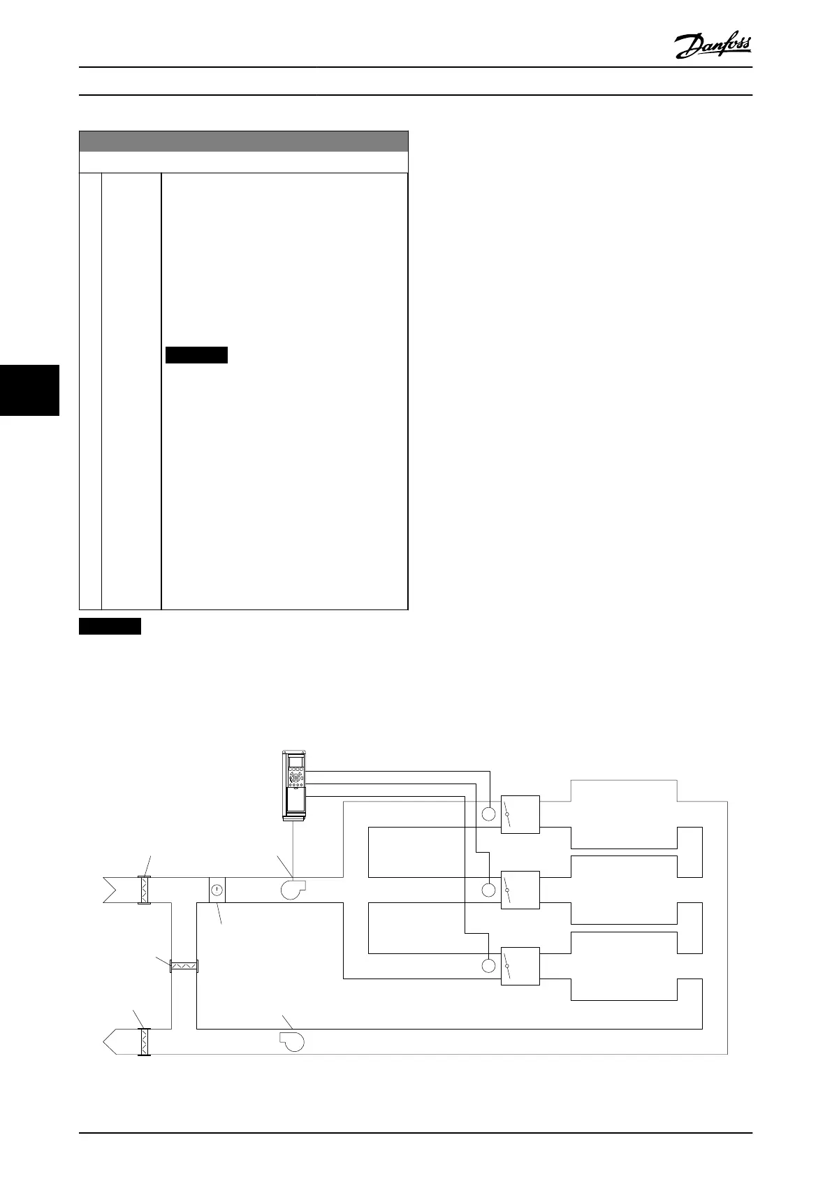
The frequency converter can be configured to handle multi
zone applications. 2 different multi-zone applications are
supported:
•
Multi zone, single setpoint
•
Multi zone, multi setpoint
The difference between the 2 is illustrated by the following
examples:
Example 1 – Multi zone, single setpoint
In an office building, a VAV (variable air volume) VLT HVAC
Drive system must ensure a minimum pressure at selected
VAV boxes. Due to the varying pressure losses in each
duct, the pressure at each VAV box cannot be assumed to
be the same. The minimum pressure required is the same
for all VAV boxes. This control method can be set up by
setting parameter 20-20 Feedback Function to option [3],
Minimum, and entering the desired pressure in
parameter 20-21 Setpoint 1. The PID Controller increases the
speed of the fan if any one feedback is below the setpoint
and decrease the speed of the fan if all feedbacks are
above the setpoint.
P
P
P
P
P
P
VAV
Box
Zone 1
Damper
Cooling/
heating coil
Supply
air fan
Return air fan
Damper
Damper
Zone 2
Zone 3
VAV
Box
VAV
Box
130BA353.10
Illustration 6.17
How to Programme VLT HVAC Drive FC 102 Operating Instructions
106 MG11F402 - Rev. 2013-12-16
66
 Loading...


