mm
10
20
30
40
50
60
70
[10]
[15]
[5]
[0.04]
[0.08]
[0.12]
[0.16]
[0.2] [0.04] [0.08]
[0.12]
[0.16] [0.2] [0.24]
[0.28]
[in]
AA
A
B
C
D
P005 598E
0
400
200
600
1200
800
1000
1400
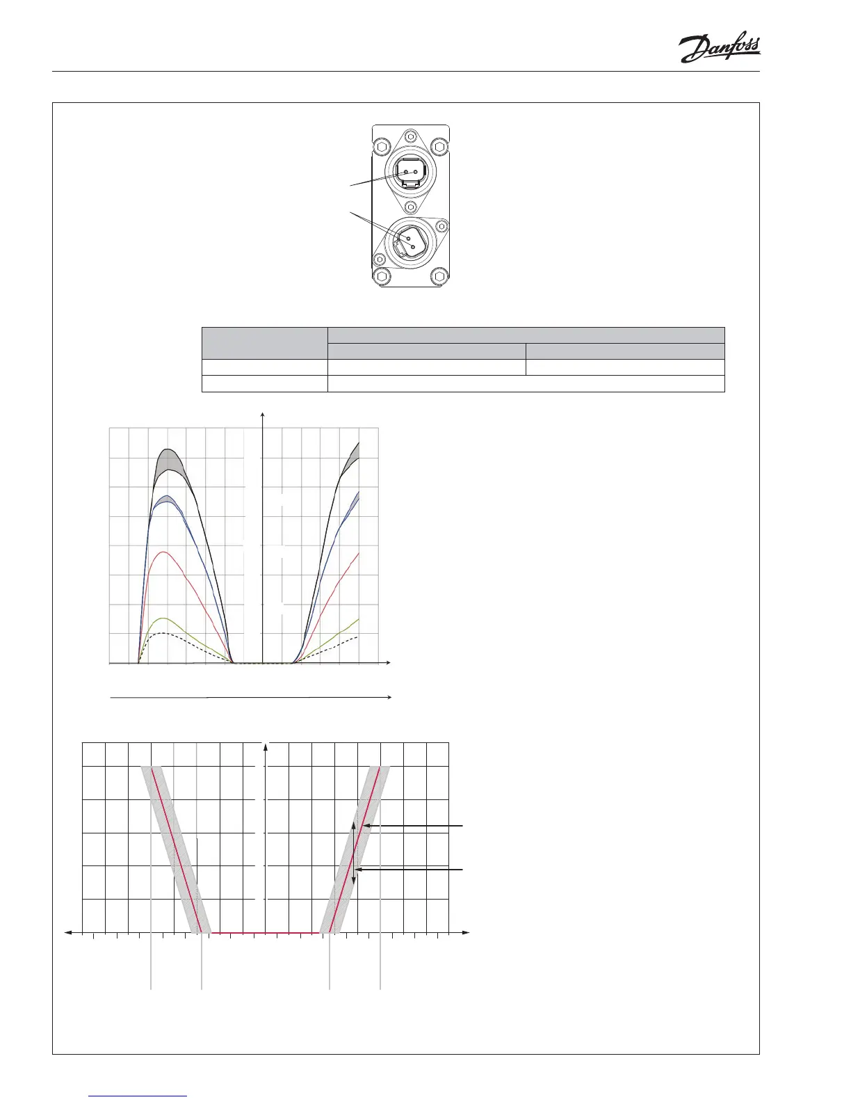
Current in mA
Spool stroke, mm
5
4
3
2
1
1600
400
200
600
1200
800
1000
1400
1600
200
100
300
600
400
500
700
800
200
100
300
600
400
500
700
800
@ 12V
@ 24V
P301 775.A
Ideal curve
Hysteresis
280/560 mA 500/1000 mA280/560 mA500/1000 mA
Parameter
Control range
12 V 24 V
Current 1 - 1200 mA 0 - 600 mA
Pressure control range 5 to 15 bar [72.5 to 217.5 psi]
2 L1407359 • Rev AB • Nov 2014 © Danfoss, 2014-11
The ideal curve is determined by the main spool neutral spring.
The hysteresis is aected by viscosity, friction, ow forces, dither frequency and modulation frequency.
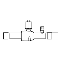
Aktivering
Activation
Betätigung
Commande
Deutsch Version

 Loading...