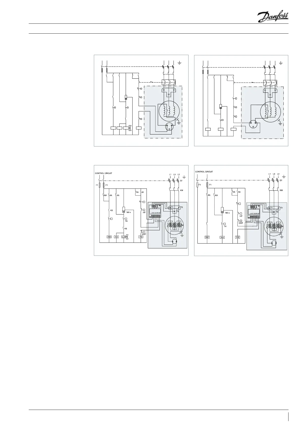
Electrical data, connections and wiring
Compressor models SM / SZ 175 – 185 R and C version
Legends
Compressor models SY 240 - 300 - 380 & SM/SZ-185 (P, X, Y versions)
Fuses .............................................................................................................F1
Compressor contactor ............................................................................ KM
Control relay ..............................................................................................KA
Safety lock out relay ..................................................................................KS
Optional short cycle timer (3 min) ...................................................180 s
External overload protection ..................................................................F2
Pump-down pressure switch ..................................................................LP
High pressure safety switch....................................................................HP
Control device ............................................................................................TH
Liquid Line Solenoid valve ..................................................................LLSV
Discharge gas thermostat ................................................................... DGT
Fused disconnect ......................................................................................Q1
Motor safety thermostat ...................................................................... thM
Compressor motor .................................................................................... M
Motor Protection Module .................................................................. MPM
Thermistor chain..........................................................................................S
Safety pressure switch ........................................................................... LPS
CONTROL CIRCUIT
F1
F1
KA KAKA
HP
LPS
T1
T2
T3
KM
DGT
KS
KS
1
2
M
ThM
KS
KS
KA
KM
KM
LLSV
180s
TH
F2
Q1
L1 L3 L2
A1
A2
A3
Wiring diagram with pump-down cycle
LP
F1
F1
KA
KA
KA
HP
T1
T2
T3
KM
DGT
KS
KS
1
2
TH
KS
LPS
KA
KM
180s
F2
Q1
L1 L3 L2
M
ThM
A1
A2
A3
Wiring diagram without pump-down cycle
A1
A3
A2
MPM
S
LPS
Wiring diagram with pump-down cycle
LP
A1
A3
A2
MPM
S
KS
Wiring diagram without pump-down cycle
LPS
21AB237986441643en-010801
Application Guidelines