4
Installation Instructions
GB
!
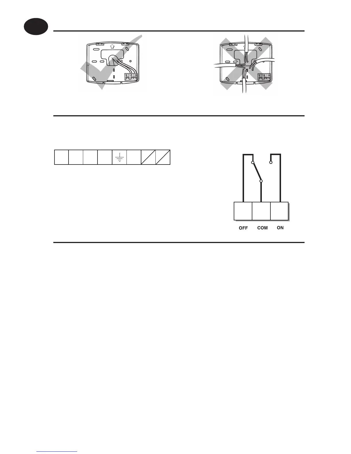
Some existing thermostats will have a Neutral and/or Earth wire connected. These
are not required by the TP5001 (battery models) and must NOT be connected to any
TP5001 terminals. Instead they should be made electrically safe and coiled in the
recess at the back of the TP5001.
Cable Access
Wiring - TP5001
Models with remote sensor inputs
TP5001A and TP5001MA incorporate an input which can be used to
connect one of the following:
1) remote room temperature sensor (sold as accessory).
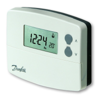
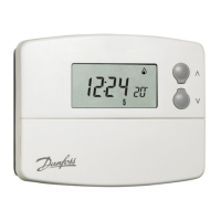
Battery Installation
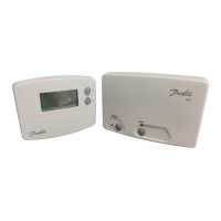
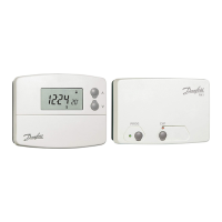
When installing the batteries in the TP5001 and TP5001 RF please
ensure that the correct polarity is observed as per the markings on the
inside of the battery compartment.
Important: After installing the batteries press and release the RESET
button to start the unit. The display may appear blank until this is
done. Once the button is released the display will appear. All date, time,
programming and override settings are maintained for the life of the
product.
1
2
3
Output Connections,
all hard wired models
L
N
DE
S1 S2
Remote Sensor
(A version only)
M 230V Models
 Loading...