MG.20.B6.02 – VLT is a registered Danfoss trademark
77
VLT
®
2000 Series
Section 1 Section 2 Section 3
500 Address (ADDRESS)
Value:
01- 99 ✭ 01
101- 199 (01-99 echo)
Function:
Using this parameter you set the bus address for
each VLT via the control panel. However, the first tele-
gram after the voltage connection can change the
bus address. This means that address change from
the bus is no longer possible.
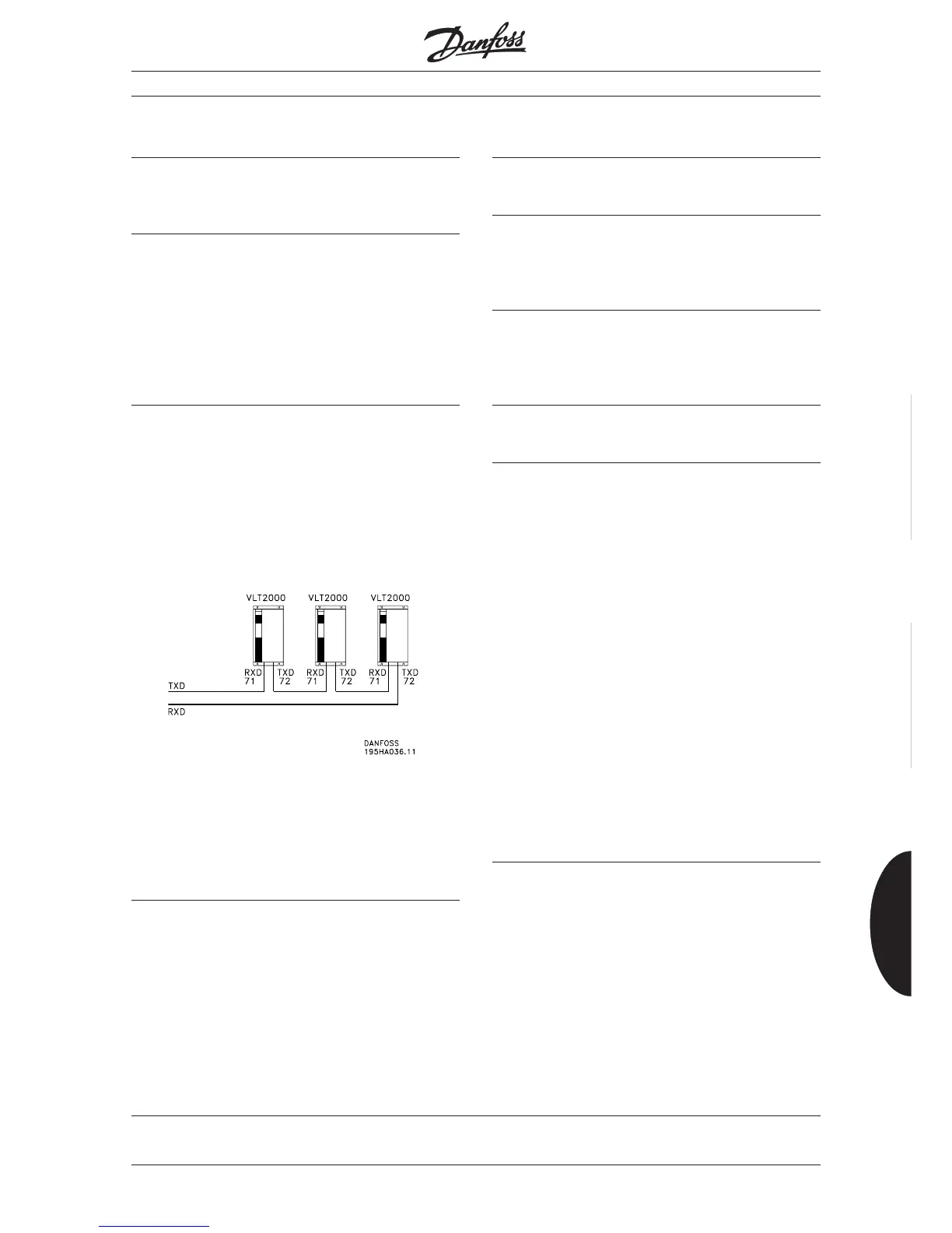
The echo function enables connection of several VLT
2000 frequency converters to the same PC.
Description:
Specify an address of each unit connected. If the PC/
PLC addresses 00, all drives connected will be written
to at the same time. The units will in this case not give
a reply to the master.
Address change via bus enables address change on
units without display.
The echo function is active on address 101-199,
shown as 01-99 ECHO. The ring is built up by
connecting Tx on the first VLT to Rx on the next VLT.
The last unit’s Tx is connected to Rx on the PC. Ter-
minal 20 (frame) must be connected throughout, but
with the PC connected at only one end.
501 Bit/sec. baud rate (BAUD RATE)
Value:
300, 600, 1200, ✭ 1200
Function:
Using this parameter you can set the speed at which
a character is transmitted via the RS 232 port. It is
defined as the number of bits transmitted per second.
Description:
The transmission rate of the VLT frequency converter
must be set in accordance with the transmission rate
of the PLC/PC applied. The transmission rate can
only be altered via the control panel.
502 Data readout (DATA READOUT)
Value:
✭ [0] Reference (REFERENCE %) ....................... %
[1] Frequency (FREQUENCY Hz) ................... Hz
[2] Display/Feedback (FEEDBACK UNIT) ... "unit"
[3] Current (CURRENT) .................................... A
[4] Torque (TORQUE %) .................................. %
[5] Power (POWER kW)..................................kW
[8] Output voltage (OUT VOLT) ..........................V
[9] DC voltage (DC BUS) ...................................V
[10] Motor thermal load (RTR (M)) ..................... %
[11] VLT therm ETR (INVERT THERM) .............. %.
[12] Digital input (DIG. IN/CODE) ........ binary code
[13] Analogue input 1 (ANALOGUEin1) in terminal 53
[14] Analogue input 2 (ANALOGUEin2) in terminal 60
[15] Warning parameter (WARNING CODE)
binary code
[16] Control word (CONTROL WORD) - see page 57.
[17] Status word (STATUS WORD) - see page 56.
[18] Alarm parameter (ALARM CODE) binary code
[19] Software version no. .......................... 4 digits
Description:
Menu 502 can only be selected from the bus. These
values are read-only values.
The PC/PLC may prompt for a value from an index
between 0 and 19.
✭ = Factory setting. Text in ( ) = Display text. The figures in [ ] are used in bus communication.
Description of parameters
■
■
■