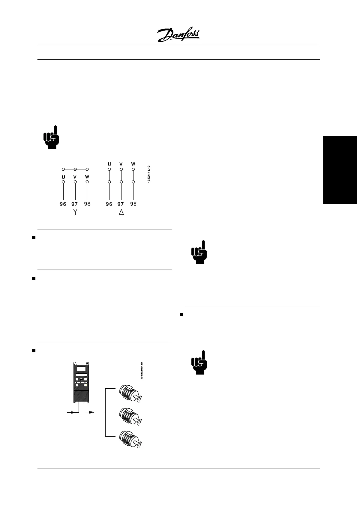
All types of three-phase asynchronous standard mo-
tors can be connected to an adjustable frequency
drive. Normally, small motors are star-connected
(230/400 V, / Y), while large motors are delta-con-
nected (400/690 V, / Y). The correct connection
mode and voltage can be read from the motor name-
plate.
NOTE
In motors without phase insulation paper,
an LC filter should be fitted on the output
of the adjustable frequency drive.
Direction of motor rotation
To change the direction of motor rotation, switch any
two phases at the drive output or at motor terminals.
Motor thermal protection
The electronic thermal relay in UL approved variable
frequency drives has received the UL approval for sin-
gle motor protection, when parameter 128 Motor ther-
mal protection has been set for ETR Trip and
parameter 105 Motor current, I
M, N
has been program-
med to the rated motor current (see motor nameplate).
Parallel connection of motors
The adjustable frequency drive is able to control sev-
eral motors connected in parallel. If the motors are to
have different rpm values, use motors with different
rated rpm values. Motor rpm is changed simultane-
ously, which means that the ratio between the rated
rpm values is maintained across the range. The total
current consumption of the motors is not to exceed the
maximum rated output current I
INV
for the adjustable
frequency drive.
Problems may arise at the start and at low rpm values
if the motor sizes are widely different. This is because
the small motors' relatively high ohmic resistance in
the stator calls for a higher voltage at the start and at
low rpm values.
In systems with motors connected in parallel, the elec-
tronic thermal relay (ETR) of the adjustable frequency
drive cannot be used as motor protection for the indi-
vidual motor. For this reason, further motor protection
must be used, such as thermistors in each motor or an
individual thermal relay, for example (circuit breakers
are not a suitable means of protection).
NOTE
Parameter 107 Automatic motor adapta-
tion, AMT cannot be used when motors
are connected in parallel. Parameter 101
Torque characteristic must be set to Spe-
cial motor characteristics [8] when motors
are connected in parallel.
Motor cables
See Technical data for correct dimensioning of motor
cable cross-section and length. Always comply with
national and local regulations on cable cross-section.
NOTE
If an unshielded/unarmored cable is used,
some EMC requirements are not com-
plied with, see EMC test results in the De-
sign Guide.
If the EMC specifications regarding emissions are to
be complied with, the motor cable must be shielded/
armored unless otherwise stated for the RFI filter in
question. It is important to keep the motor cable as
short as possible so as to reduce the noise level and
leakage currents to a minimum. The motor cable shield
must be connected to the metal cabinets of the adjust-
VLT
®
2800 Series
MG.27.A2.22 - VLT
®
is a registered Danfoss trademark 19
Installation

 Loading...


