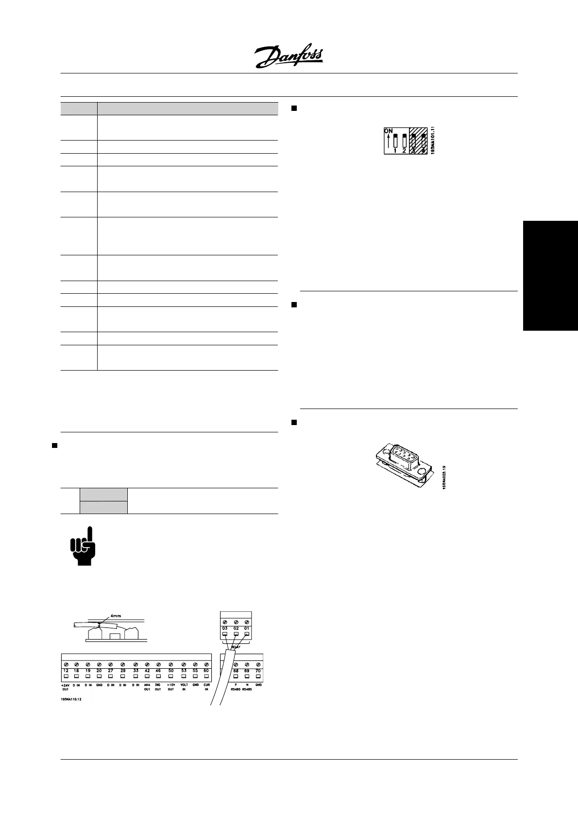
No. Function
01-03 Relay outputs 01-03 can be used for
indicating status and alarms/warnings.
12 24 V DC voltage supply.
18-33 Digital inputs.
20, 55 Common frame for input
and output terminals.
42 Analog output for displaying frequency,
reference, current or torque.
46
1
Digital output for displaying status,
warnings or alarms, as well as
frequency output.
50 +10 V DC supply
voltage for potentiometer or thermistor.
53 Analogue voltage input 0-10 V DC.
60 Analogue current input 0/4 - 20 mA.
67
1
+ 5 V DC supply voltage
to Profibus.
68, 69
1
RS-485, Serial communication.
70
1
Frame for terminals 67, 68 and 69.
Normally, this terminal is not to be used.
1. The terminals are not valid for DeviceNet/CANopen.
See also the DeviceNet manual, MG.90.BX.YY for fur-
ther details.
Relay connection
See parameter 323 Relay output for programming of
relay output.
Nr.
01 - 02 1 - 2 make (normally open)
01 - 03
1 - 3 break (normally closed)
NOTE
Please note that the cable jacket for the
relay must cover the first row of control
card terminals - otherwise the galvanic
isolation (PELV) cannot be maintained.
Max. cable diameter: 4 mm. See drawing.
Profibus DIP switches setting
The dip switch is only on the control card with Profibus
DP communication. The switch position shown is the
factory setting. Switches 1 and 2 are used as cable
termination for the RS-485 interface. If the adjustable
frequency drive is located as the first or last (or only)
unit in the bus system, switches 1 and 2 must be ON.
On the remaining adjustable frequency drives,
switches 1 and 2 must be OFF. Switches 3 and 4 are
not applied.
VLT Software Dialog
Connection to terminals 68-70 or
Sub D:
-
PIN 3 GND
-
PIN 8 P-RS 485
-
PIN 9 N-RS 485
Sub D plug
An LCP 2 control unit can be connected to the Sub D
plug on the control card. Ordering number: 175N0131.
The LCP control unit with ordering number 175Z0401
is not to be connected.
VLT
®
2800 Series
MG.27.A2.22 - VLT
®
is a registered Danfoss trademark 23
Installation

 Loading...


