Description of choice:
R
S
can be set as follows:
1. Use the factory settings of R
S
which the ad-
justable frequency drive itself chooses on the
basis of the motor nameplate data.
2. The value is stated by the motor supplier.
3. The value is obtained through manual meas-
urements: R
S
can be calculated by measur-
ing the resistance R
PHASE-PHASE
between two
phase terminals. Where R
PHASE-PHASE
is low-
er than 1-2 Ohms (typical for motors > 7.5
HP, 400 V), a special Ohm-meter should be
used (Thomson-bridge or similar). R
S
= 0.5 x
R
PHASE-PHASE
.
4. R
S
is set automatically when AMT has been
completed. See parameter 107 Auto motor
tuning.
109
Stator reactance X
S
(STATOR REACTANCE)
Value:
0.00 - X,XX
Depends on choice of motor
Function:
After parameters 102-106 Nameplate data are set, a
number of parameters are adjusted automatically, in-
cluding stator reactance X
S
. The shaft performance
can be improved by fine-tuning R
S
and X
S
; see proce-
dure below.
Description of choice:
X
S
can be set as follows:
1. The value is stated by the motor supplier.
2. The value is obtained through manual meas-
urements; X
S
is obtained by connecting a
motor to line power and measuring the
phase-phase voltage U
M
and the idle current
.
X
s
=
U
M
3×
I
ϕ
−
X
L
2
X
L
: See parameter 142.
3. Use the factory settings of X
S
, which the ad-
justable frequency drive itself chooses on the
basis of the motor nameplate data.
117 Resonance damping
(resonance damping)
Value:
OFF 100 [OFF 100]
Off [OFF]
Function:
It is possible to optimize the resonance damping in CT
mode. The grade of the influence is adjusted in this
parameter.
The value may be set between 0% (OFF) and 100%.
100% corresponds to 50% reduction of U/F ratio.
Default value is OFF.
Internal settings (fixed):
The resonance filter is active from 10% of nominal
speed and above.
In this case 5Hz and above.
Speed to go from 0 to nominal flux level: 500ms
Speed to go from nominal to 0 flux level: 500 ms
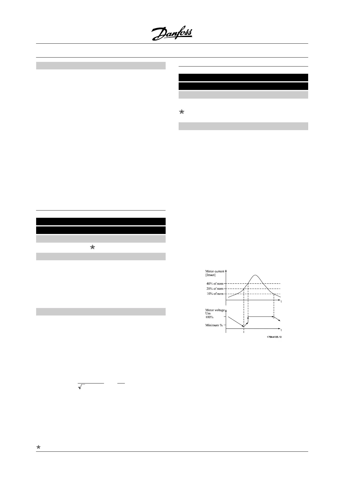
Description of functionality:
The filter monitors the active motor current and
changes the motor voltage according to the figure be-
low. The filter reacts on levels referring to the nominal
motor current.
If the active motor current is below 10%, the motor
voltage will be decreased by the speed mentioned
above until the voltage reaches the setting for Par.
117. If the active motor current comes over 20% the
voltage will be increased by the above-mentioned
speed. If the active motor current reaches 40% the
motor voltage will be increased immediately to normal
motor voltage.
The reduction in motor voltage depends on the pa-
rameter 117 setting.
VLT
®
2800 Series
= factory setting, () = display text, [] = value for use in communication via serial communication port
44 MG.27.A2.22 - VLT
®
is a registered Danfoss trademark

 Loading...


