13
MG.60.N1.22 - VLT is a registered Danfoss trademark
VLT
®
5000 / VLT
®
6000 HVAC / VLT
®
8000 AQUA
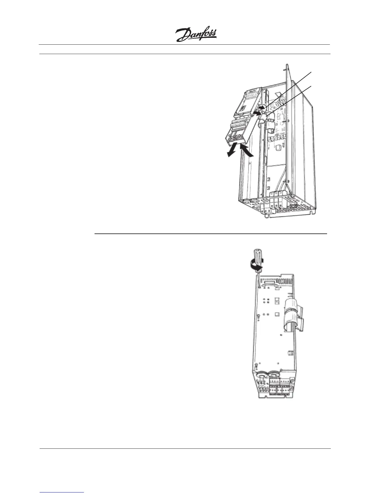
• Lift control card cassette from bottom.
• Unplug two ribbon cables (A) and (B)
from control board.
• Unhinge cassette at top to remove.
3. Remove
Cassette
and Ribbon
Cables
NOTE
Ribbon cables will need to be
reconnected to same connec-
tions from which removed.
4. Chassis
Ground
Connections
• Location of holes to mount grounding
strips can vary with drive configuration.
When applicable, remove mounting
screws and washers located in chassis
using Torx T-20 screw driver and save
for reassembly. Otherwise, grounding
strips attach with screws and washers
provided, as shown in step 5.
NOTE
Ground strips are used on 208 V
drives of 22 kW (30 HP) or less
and on 460 V drives of 45 kW
(60 HP) or less. For all other
drives, go to step 6.
(A)
(B)
 Loading...


