17
MG.60.N1.22 - VLT is a registered Danfoss trademark
VLT
®
5000 / VLT
®
6000 HVAC / VLT
®
8000 AQUA
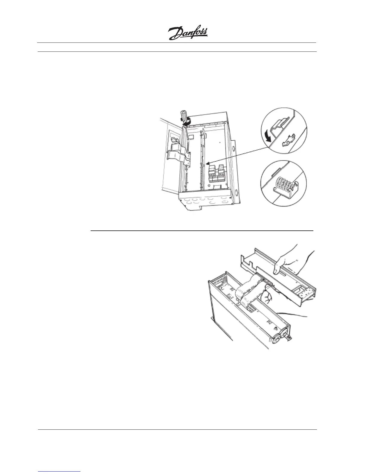
• Connect ribbon cables.
• Connect control card cassette to hinge
at top of drive and fit into chassis.
14. Install
Ribbon
Cables
NOTE
Ribbon cables must be recon-
nected to same connections from
which removed.
IP20/NEMA 1 and IP54/NEMA 12
• Spring tension clip (A) is used as a cable
strain relief and ground point for
shielded cable.
• Insert clip through inner wall of chassis
at slot provided.
• Compress spring into clip at outer wall
of chassis.
13. Install
Spring
Tension
Clip
(A)
 Loading...


