VLT
®
8000 AQUA
Installation
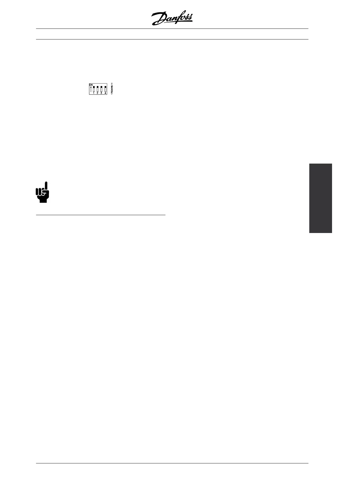
■ Switches 1-4
The dipswitch is located on the control card. It is used
for serial communication and external DC supply.
The switching position shown is the factory setting.
Switch 1 has no function.
Switches 2 and 3 are used for terminating an RS
485 interface, serial communication. In the first
and the last frequency converter, switches 2 and
3 must be ON. In the other frequency converter,
switches 2 and 3 must be OFF.
Switch 4 is used if an external 24 V DC supply is required
for the control terminals. Switch 4 separates the
common potential for the internal 24 V DC supply from
the common potential of the external 24 V DC supply.
NB!:
Please note that when Switch 4 is in position
"OFF", the external 24 V DC supply is galvanically
isolated from the frequency converter.
MG.83.A2.02 - VLT is a registered Danfoss trademark
79