-
N O T I C E
All frequency/current limit points from the motor nameplate or motor datasheet must be programmed.
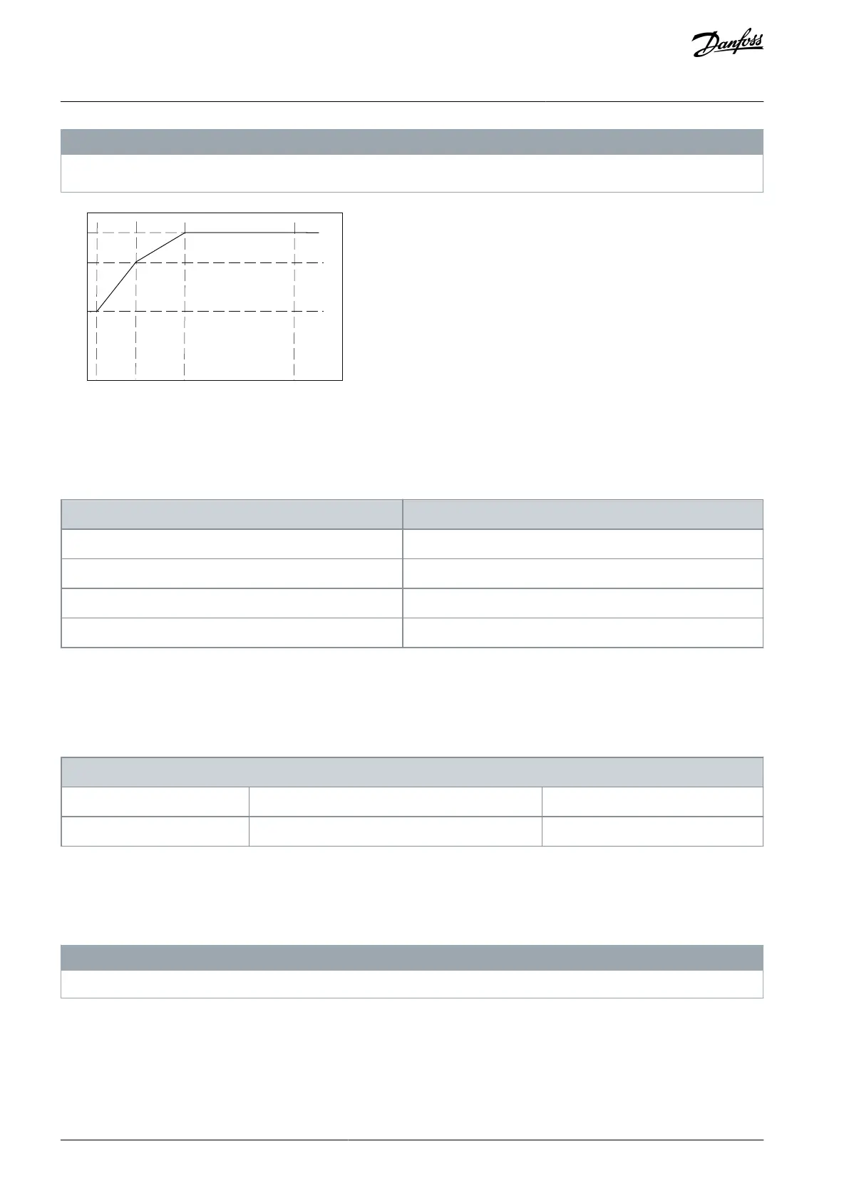
Illustration 38: Example of ATEX ETR Thermal Limitation Curve
x-axis: f
m
[Hz]
y-axis: I
m
/I
m,n
x 100 [%]
Table 144: Interpolation Points
Parameter 1-98 ATEX ETR interpol. points freq.
Parameter 1-99 ATEX ETR interpol. points current
All operating points underneath the curve are allowed continuously. Above the line, however, these are only allowed for a limited
time calculated as a function of the overload. When machine current is greater than 1.5 times the rated current, shutdown is imme-
diate.
Parameter 1-99 ATEX ETR Interpol. Points Current
Table 145: Parameter 1-99 ATEX ETR Interpol. Points Current
1-99 ATEX ETR Interpol. Points Current
Default value: Size related
Parameter type: Range, 0 - 100%, Array [4]
Change during operation: True
Definition of the thermal limitation curve. For example, see parameter 1-98 ATEX ETR Interpol. Points Freq.
Use the 4 current points [A] from the motor nameplate. Calcualte the values as percentage of nominal motor current, I
m
/I
m,n
x 100
[%], and enter the values into this array.
Together with parameter 1-98 ATEX ETR Interpol. Points Freq., these constitute a table (f [Hz], I [%]).
N O T I C E
All frequency/current limit points from the motor nameplate or motor datasheet must be programmed.
AU275636650261en-000101 / 130R0334106 | Danfoss A/S © 2022.12
Parameter Descriptions
VLT AutomationDrive FC 301/302
Programming Guide
 Loading...


