FC 300 Design Guide
Introduction to FC 300
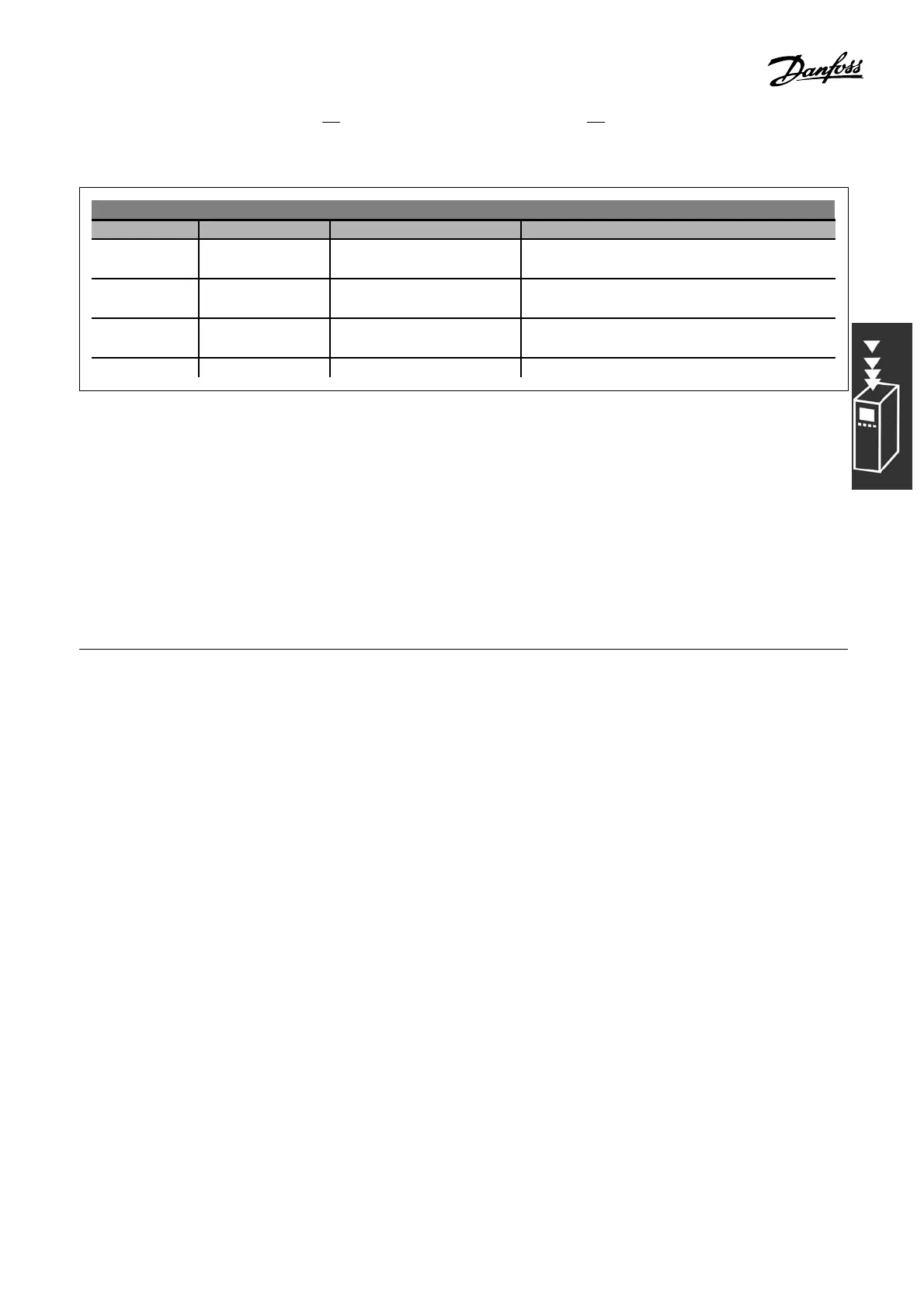
Cable lengths a nd RFI performance
FC 30x Filter Supply voltage RFI compliance at max. motor cable lengths
FC 301
FC 302
With A2 filter 200 - 240 V / 380 - 500 V /
380 - 480 V
<16 ft (5 m) EN 55011 Group A2
FC 301 With A1/B 200 - 240 V / 380 - 480 V <131 ft (40 m) EN 55011 G roup A1
<33 ft (10 m) EN 55011 Group B
FC 302 With A1/B 200 - 240 V / 380 - 500 V <492 ft (150 m) EN 55011 Group A1
<131 ft (40 m) EN 55011 Group B
FC 302 No RFI filter 550 - 600 V Not compliant with EN 55011
In certain instances, shorten the motor cable to comply with EN 55011 A1 and EN 55011 B.
Copper (140/1 67° F, 60/ 75°C) conductors recommended.
Aluminum conductors
Aluminum conductors are not recommended. Terminals can accept aluminum conductors but
the conductor surface must be clean and the oxidation m ust be removed and sealed by neutral
acid-free Vaseline grease before the conductor is connected.
Furthermore, the terminal screw must be retigh tene d after two days due to the softness of the a luminum. It
is crucial to keep the connection a gas-tight joint, otherwise the aluminum surface will oxi dize again.
Digital inputs:
Programmable digital inputs ................................................................... FC 301: 4 (5) / FC 302: 4 (6)
Terminal number ....................................................................................... 18, 19, 27
1)
,29
1)
, 32, 33 ,
Logic ............................................................................................................................ PNP or NPN
Voltage level .................................................................................................................. 0 -24VDC
Voltage level, logic’0’ PNP ................................................................................................... < 5 V DC
Voltage level, logic’1’ PNP ................................................................................................. > 10 V DC
Voltage level, logic ’0’ NPN
2)
............................................................................................ > 19 V DC
Voltage level, logic ’1’ NPN
2)
............................................................................................. < 14 V DC
Maximum voltage on input ................................................................................................... 28 V DC
Input resistance, R
i
...................................................................................................... approx. 4 kΩ
Safe stop Terminal 37
2)
:
Term inal 37 is fixed PNP logic
Voltage level .................................................................................................................. 0 -24VDC
Voltage level, logic’0’ PNP .................................................................................................... < 4 V DC
Voltage level, logic’1’ PNP ................................................................................................... >15 V DC
Nominal input current at 24 V ........................................................................................... 50 mA rms
Nominal input current at 15 V ........................................................................................... 80 mA rms
Input capacitance .................................................................................................................. 400 nF
All digital inputs are galvanically isolated from the supply voltage (PELV) and other high-voltage te rminals.
1) Terminals 27 and 29 can also b e programmed as outp u t.
2) Exc ept safe stop input Terminal 37.
3) Terminal 37 is only available in FC 302. It can only be used as safe stop input. Terminal 37 is suita ble
for category 3 installations accord ing to EN 954-1 (safe stop according to category 0 EN 60204-1) as
required by the EU Machinery Directive 98/3 7/EC. Terminal 3
7 and the Safe Stop function are designed in
57
MG.33.B3.22 - VLT is a registered Danfoss trademark
 Loading...


