FC 300 Design Guide
How to Program
" Parameters: Smart Logic
Control
" 13-** Prog. Features
The Smart Logic Control ler (SLC) is essentially
a sequence of user-defined actions (see
par. 13-52) executed by the SLC when the
associated user-defined event (see par. 13-51)
is evaluated as TRUE by the SLC.
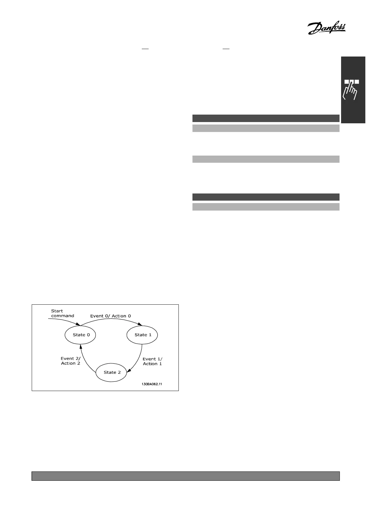
Events and actions are each numbered and are
linked together in pairs. This means that when
event [0] is fulfilled (attains the value TRUE),
action [0] is executed. After this, the conditions of
event [1] will be evaluated and if evaluated TRUE,
action [1] will be executed and so on.
Only one event will be evaluated at any time. If an
event is evaluated as FALSE, nothing happens (in the
SLC) during the current sc an interval and no other
events will be evaluated. This means that when the
SLC starts, it evaluates event [0] (and only event
[0]) each scan interval. Only when event [0] is
evaluated TRUE will the SLC execute action [0] and
start evaluating event [1]. It is possible to program
from 1 to 6 events and actions. When the last event
/ action has been executed, the sequence starts over
again from event [0] / action [0]. The illustration
showsanexamplewiththreeevents/actions:
Starting and stopping the SLC:
Starting and stopping the SLC can be done by
selecting "On [1]" or "Off [0]" in par. 13-50. The
SLC always starts in state 0 (where it evaluates
event[0]). If the drive is stopped or coasted by
any means (either via digital input, field bus or
other), the SLC automatically stops. If the drive
is started by any mean s (either via digital input,
field bus or other), the SLC also starts (provided
that "On [1]" is selected in par. 13-50).
" 13-0* SLC Settings
The settings are used for activating, deactivating
and resetting the S mart Logic Control.
13-50 SL Controller Mode
Option:
*
Off [0]
On [1]
Function:
Select On [1] to enable the Smart Logic
Controller to start when a start command is
present (i.e. via a digital input).
13-01 Start Event
Option:
FALSE [0]
TRUE [1]
Running [2]
In range [3]
On reference [4]
Torq ue l imi t [5 ]
Current limit [6]
Out of current range [7]
Below I low [8]
Above I high [9]
Below speed low [11]
Above speed high [12]
Out of feedb. range [13]
Below feedb. low [14]
Above feedb. high [15]
Thermal warning [16]
Mains out of range [17]
Reverse [18]
Warning [19]
Alarm (trip) [20]
Alarm (trip lock) [21 ]
Comparator 0 [22]
Comparator 1 [23]
Comparator 2 [24]
Comparator 3 [25]
Logic rule 0 [26]
Logic rule 1 [27]
Logic rule 2 [28]
Logic rule 3 [29]
Digital input DI18 [33]
Digital input DI19 [34]
Digital input DI27 [35]
*
default setting ()display text []value for use in communication via serial communication port
195
MG.33.B
3.22 - VLT is a registered Danfoss trademark
 Loading...


