VLT
®
FCD Series
10 [1-10] log values are denoted. The lowest log
number [1] contains the latest/most recently saved
data value, and the highest log number [10] contains
the oldest data value.
Description of choice:
Read out as one value.
617
617 Fault log: Value
(F.LOG: VALUE)
Value:
[Index 1 - 10] Value: 0 - 9999
Function:
In this parameter it is possible to see at which value
a trip occurred. The unit of the value depends on
which alarm is active in parameter 615
Fault log:
Fault code.
Description of choice:
Read out as one value.
618
618 Reset of kWh counter
(RESET KWH COUNT)
Value:
✭No reset (DO NOT RESET)
[0]
Reset (RESET COUNTER)
[1]
Function:
Resetting parameter 602 kWh counter to zero.
Description of choice:
If Reset [1]is selected and you press the [OK] key,
the frequency converter’s kWh counter is reset to
zero. This parameter cannot be selected via serial
communication.
NB!:
When the [OK]
key is activated, the counter is reset to zero.
619
619 RESET RUNNING HOURS COUNTER
(RESET RUN. HOUR)
Value:
✭No reset (DO NOT RESET)
[0]
Reset (RESET COUNTER)
[1]
Function:
Resetting of parameter 601 Hours run to zero.
Description of choice:
If Reset [1]is selected and you press the [OK] key,
the frequency converter’s parameter 601 is reset to
zero Hours run. This parameter cannot be selected
via serial communication.
NB!:
When the [OK]
key is activated the parameter is reset to zero.
620
620 Operation Mode
(OPERATION MODE)
Value:
✭Normal operation (NORMAL OPERATION)
[0]
Control card test (CONTROL CARD TEST)
[2]
Initialise (INITIALIZE)
[3]
Function:
In addition to its normal function, this parameter can
be used to test the control card.
There is also the opportunity to perform an initialisa-
tion at the factory setting for all parameters in all
Setups, with the exception of parameters 500 Ad-
dress, 501 Baudrate, 600-605 Operating data and
615-617 Fault log.
Description of choice:
Normal function [0] is used for normal operation of
the motor.
Control card test [2] is selected if you wish to check
the control card’s analog/digital inputs, analog/digital
outputs, relay outputs and 10 V and 24 V voltages.
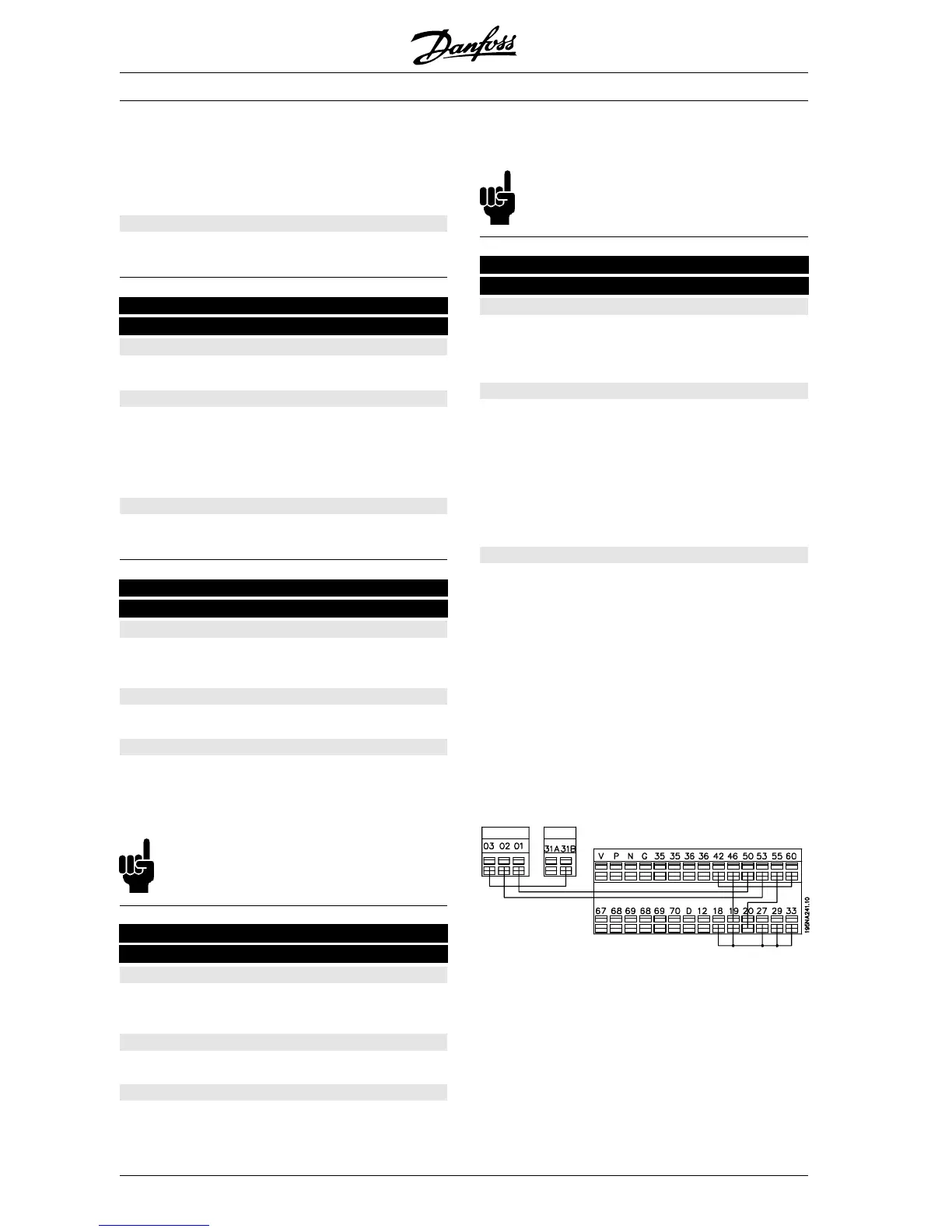
The test is performed as follows:
18 – 19 – 27 - 29 - 33 - 46 are connected.
20 - 55 are connected.
42 - 60 are connected.
01 - 50 are connected.
02 - 53are connected.
03 - 31B are connected.
Use the following procedure for the control card test:
1. Select control card test.
2. Disconnect the mains voltage and wait until the
light in the display has disappeared.
3. Mount according to drawing and description.
4. Connect the mains voltage.
5. The frequency converter automatically under-
takes a test of the control card.
✭
= factory setting. () = display text [] = value for use in communication via serial communication port
MG.04.A1.02 - VLT is a registered Danfoss trade mark
114
 Loading...


