VLT
®
FCD Series
126 DC brake time
(DC BRAKING TIME)
Value:
0 - 60 sec.
✭ 10 sec
Function:
In this parameter, the DC brake time is set at which
parameter 132 DC brake voltage is to be active.
Description of choice:
Set the required time.
127 DC brake cut-in frequency
(DC BRAKE CUT-IN)
Value:
0.0 (OFF) - par. 202
Output frequency high limit, f
MAX
✭ OFF
Function:
In this parameter, the DC brake cut-in frequency
is set at which the DC brake is to be activated
in connection with a stop command.
Description of choice:
Set the required frequency.
128 Thermal motor protection
(MOT.THERM PROTEC)
Value:
✭No protection (NO PROTECTION)
[0]
Thermistor warning
(THERMISTOR WARN)
[1]
Thermistor trip (THERMISTOR TRIP)
[2]
ETR warning 1 (ETR WARNING 1)
[3]
ETR trip 1 (ETR TRIP 1)
[4]
ETR warning 2 (ETR WARNING 2)
[5]
ETR trip 2 (ETR TRIP 2)
[6]
ETR warning 3 (ETR WARNING 3)
[7]
ETR trip 3 (ETR TRIP 3)
[8]
ETR warning 4 (ETR WARNING 4)
[9]
ETR trip 4 (ETR TRIP 4)
[10]
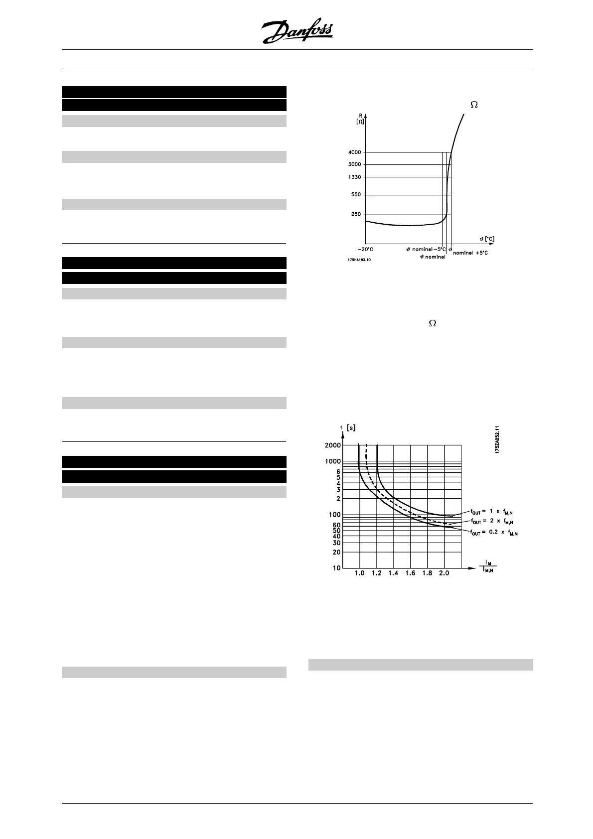
Function:
The frequency converter can monitor the motor
temperature in two different ways:
- Via a PTC thermistor that is mounted on the motor.
The thermistor is connected between terminal 31a
/ 31b. Thermistor is to be selected if a possibly
integrated thermistor in the motor is to be able
to stop the frequency converter if the motor
overheats. The cut-out value is 3 k
.
If a motor features a Klixon thermal switch instead,
this can also be connected to the input. If
motors operate in parallel, the thermistors/thermal
switches can be connected in series (total
resistance lower than 3 k
).
- Thermal load calculation (ETR - Electronic
Thermal Relay), based on present load and
time. This is compared with the rated motor
current I
M,N
and rated motor frequency f
M,N
.
The calculations take into account the need for
lower loading at low speeds due to the motor’s
internal ventilation being reduced.
ETR functions 1-4 correspond to Setup 1-4. ETR
functions 1-4 do not begin to calculate the load until
you switch to the Setup in which they have been
selected. This means that you can use the ETR function
even when changing between two or more motors.
Description of choice:
Select No protection [0] if you do not want a warning
or trip when a motor is overloaded.
Select Thermistor warning [1] if you want a warning
when the connected becomes too hot.
Select Thermistor trip [2] if you want a trip when the
connected thermistor becomes too hot.
✭
= factory setting. () = display text [] = value for use in communication via serial communication port
MG.04.B7.02 - VLT is a registered Danfoss trademark
44
 Loading...


