VLT
®
FCM Series
Installation
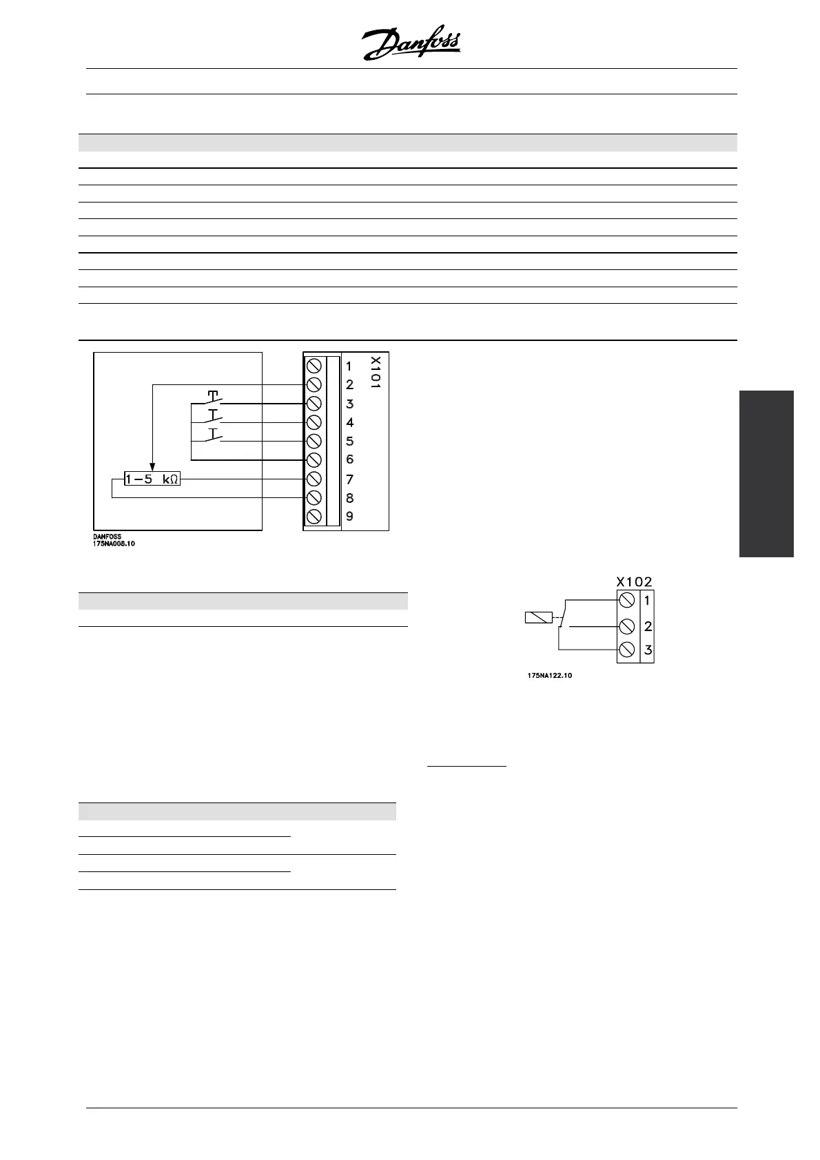
X101: Terminal block for analogue/digital con trol signals
Terminal No. Function Example
1 Analogue input (0-20 mA) Feedback signal
2 Analogue (0-10 V)/digital input 2 Speed reference
3 Digital input (or pulse) 3 Reset
4 Digital input (or precise stop) 4 Start
5 Digital input (other) 5 Jog (fixed speed)
6 24 V DC supply for digital inputs (max. 150 mA)
7 10 V DC supply for potentiometer (max. 15 mA)
80Vforterminals1-7and9
9 Analogue (0-20 mA)/digital output Fault indication
Connection diagram - factory setting
- Reset to be closed short time for resetting fault trips
- Start to be closed for changing to run mode
- Jog will run at fixed speed while closed (10 Hz)
- Speed reference (0-10 V) determines speed
while in run mode
X102: Terminal block for relay output
Terminal No. Function
1-2 Make (normally open)
1-3 Brake (normally closed)
See parameter 323 (relay output) for programming
of relay output.
X100: Terminal block for data communication
Terminal No. Function
1PRS485
2 N RS 485
for connection
to bus or PC
35VDC
40VDC
Supply for RS
485 bus
LED 300-304
LED 300 (red): Fault trip
LED 301 (yellow): Warning
LED 302 (green): Power on
LED 303-304: Communication
For PROFIBUS versions please refer to the
manual MG.90.AX.YY.
MG.03.H3.02 - VLT is a registered Danfoss trademark
13
 Loading...


