VLT
®
FCM Series
■ Ordering info for Frames and Flanges
Frame sizes and the corresponding flange sizes
for different mounting versions
Type Motor frame size Mounting version Flange size, standard
(S) [mm]
Flange size,
alternatives
*
[mm]
B5/B35 165 100/115/130/215
FCM 305 80
B14/B34 100 85/115/130
B5/B35 165 100/115/130/215
FCM 307 80
B14/B34 100 85/115/130
B5/B35 165 130/215
FCM 311 90
B14/B34 115 100/130
B5/B35 165 130/215
FCM 315 90
B14/B34 115 100/130
B5/B35 215 165/265
FCM 322 100
B14/B34 130 115/165
B5/B35 215 165/265
FCM 330 100
B14/B34 130 115/165
B5/B35 215 165/265
FCM 340 112
B14/B34 130 165
B5/B35 265 215/300
FCM 355 132
B14/B34 165 130
B5/B35 265 215/300
FCM 375 132
B14/B34 165 130
Flange size according to IEC ref. FFxxx (Dimension M), see section Dimensions
S: Available as standard shaft
*
No changes regarding shaft dimensions
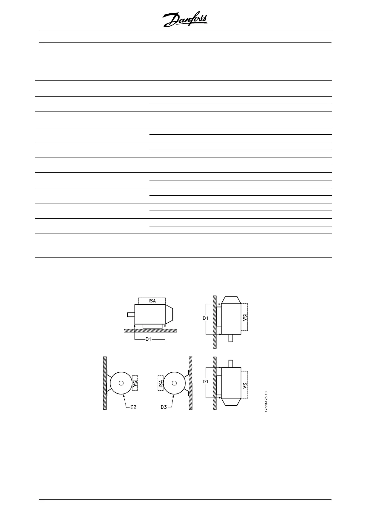
■ Ordering info for inverter box position a
nd
drain hole position
Inverter box position, always top mounted.
All drain holes are mounted with screw and
washer, IP 66 if not opened.
D1: Drain holes opposite inverter side, both
drive end and non drive end.
D2/D3: Drain holes 90° to inverter, both drive
end and non drive end.
MG.03.H3.02 - VLT is a registered Danfoss trademark
8
 Loading...


