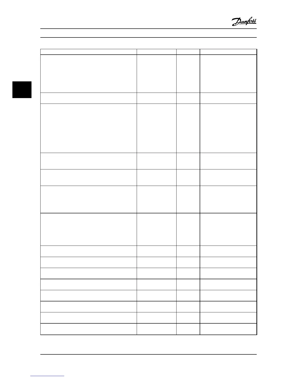
Parameter Option Default Usage
1-49 Current at Min Inductance for q-axis
20–200% 100% This parameter specifies the
saturation curve of the d- and q-
inductance values. From 20% to
100% of this parameter, the
inductances are linearly
approximated due to parameters
1-37, 1-38, 1-44, and 1-45.
1-70 PM Start Mode
[0] Rotor Detection
[1] Parking
[0] Rotor
Detection
–
1-73 Flying Start
[0] Disabled
[1] Enabled
0
Select [1] Enable to enable the
drive to catch a motor spinning
due to line drop-out. Select [0]
Disable if this function is not
required. When this parameter is
set to [1] Enable, 1-71 Start Delay
and 1-72 Start Function have no
function. 1-73 Flying Start is active
in VVC
+
mode only
3-02 Minimum Reference
-4999–4999 0 The minimum reference is the
lowest value obtainable by
summing all references.
3-03 Maximum Reference
-4999–4999 50 The maximum reference is the
lowest obtainable by summing all
references.
3-41 Ramp 1 Ramp Up Time
0.05–3600.0 s Size related Ramp-up time from 0 to rated
1-23 Motor Frequency if Asynchron
motor is selected; ramp up time
from 0 to 1-25 Motor Nominal
Speed if PM motor is selected.
3-42 Ramp 1 Ramp Down Time
0.05–3600.0 s Size related Ramp-down time from rated
1-23 Motor Frequency to 0 if
Asynchron motor is selected; ramp
down time from 1-25 Motor
Nominal Speed to 0 if PM motor is
selected.
4-12 Motor Speed Low Limit [Hz]
0.0–400 Hz 0 Hz Enter the minimum limit for low
speed.
4-14 Motor Speed High Limit [Hz]
0.0–400 Hz 100 Hz Enter the maximum limit for high
speed.
4-19 Max Output Frequency
0–400 100 Hz Enter the maximum output
frequency value.
5-40 Function Relay [0] Function relay See 5-40 Function Relay
Alarm Select the function to control
output relay 1.
5-40 Function Relay [1] Function relay See 5-40 Function Relay
Drive running Select the function to control
output relay 2.
6-10 Terminal 53 Low Voltage
0–10 V 0.07 V Enter the voltage that corresponds
to the low reference value.
6-11 Terminal 53 High Voltage
0–10 V 10 V Enter the voltage that corresponds
to the high reference value.
6-12 Terminal 53 Low Current 0–20 mA 4 mA Enter the current that corresponds
to the low reference value.
Programming VLT®HVAC Basic Drive FC 101
32 Danfoss A/S © 08/2014 All rights reserved. MG18A622
44

 Loading...


