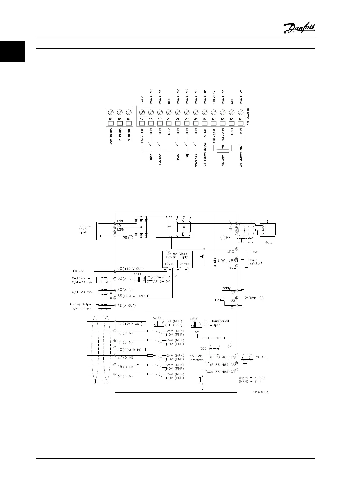
Figure 1.5 shows all control terminals of the adjustable frequency drive. Applying Start (terminal 18) and an analog reference
(terminal 53 or 60) make the adjustable frequency drive run.
Figure 1.5 Overview of Control Terminals in PNP configuration and Factory Settings
1.3.6
Power Circuit - Overview
Figure 1.6 Diagram Showing all Electrical Terminals
* Brake (BR+ and BR-) are not applicable for M1.
Quick Guide Quick Guide
8 Danfoss A/S © Rev. 2014-02-27 All rights reserved. MG02B922
1
1
 Loading...


