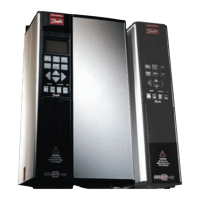
Do you have a question about the Danfoss VLT 5152 and is the answer not in the manual?
General safety guidelines for operating the frequency converter.
Precautions to prevent accidental motor starts during operation or maintenance.
Guidelines for connecting and parameterizing a mechanical brake.
Protection against motor overload using electronic thermal relay.
Heat-sink temperature monitoring and cut-out/reset points.
Short-circuit protection on motor terminals U, V, W.
Earth fault protection on motor terminals U, V, W.
Protection against over/under voltage in the intermediate circuit.
Controlled ramp-down capability during mains faults.
Drive cut-out for missing mains phase when load is applied.
Guidelines for installing the frequency converter vertically and ensuring proper cooling and clearances.
Diagrams and information on connecting power cables for different VLT 5000 enclosures.
General guidance for electrical installation, including safety precautions and terminal connections.
Instructions for connecting mains phases and high voltage testing precautions.
Importance of proper grounding due to high leakage current and safety regulations.
Utilizing electronic thermal relay for motor protection via parameter 128.
Guidelines for connecting brake cables, including screening and cross-section sizing.
Guidelines for connecting control cables, including tightening torques and grounding.
Overview of the Local Control Panel, its functions, and detachable design.
Functions of the control keys for parameter setup and local operation.
Guide to parameter setup using Menu or Quick menu modes.
Step-by-step guide to using Quick Setup for initial parameter configuration.
How to select and change parameters using the LCP keys.
Procedures for changing numeric and text parameter values.
Recommended initialization procedure using parameter 620.
Procedure for manual initialization using key combinations.
Selecting between local and remote control modes for the drive.
Defining the setup number for controlling the frequency converter's functions.
Selecting the configuration for the adjustable frequency drive based on application.
Adjusting U/f characteristics to match load torque characteristics.
Selecting the kW value corresponding to the motor's rated power.
Selecting the motor voltage matching the nameplate data.
Setting the rated motor frequency (fM,N) based on nameplate data.
Entering the rated motor current (IM,N) in Amperes for drive calculations.
Setting the rated motor speed (nM,N) for optimal slip compensation.
Algorithm for optimizing drive adjustment by measuring motor parameters.
Securing high starting torque by allowing higher current for a short period.
Setting a delay for the starting time before acceleration begins.
Selecting the function to be activated during the start delay.
Selecting the drive's function after a stop command or when frequency ramps down.
Upholding motor function or pre-heating the motor with DC current.
Setting the DC brake current activated upon a stop.
Setting the duration for the DC braking current.
Monitoring motor temperature via thermistor or calculation.
Setting the output frequency at which the motor starts.
Selecting output frequency range and direction for motor operation.
Setting a minimum motor frequency limit for operation.
Setting a maximum motor frequency limit for operation.
Setting the torque limit for motor operation.
Setting the torque limit for regenerative operation.
Selecting motor phase monitoring for reaction to missing phases.
Configuring digital input 16 for various functions like reset or stop.
Configuring digital input 17 for functions like freeze reference or pulse reference.
Configuring digital input 18 for start functions.
Configuring digital input 19 for reversing functions.
Configuring digital input 27 for functions like coasting stop or quick-stop.
Configuring digital input 29 for setup choice or jog functions.
Configuring digital input 32 for setup choice or speed up functions.
Configuring digital input 33 for setup choice or speed down functions.
Selecting options for analog input 53, including reference and feedback.
Selecting functions for analog input 60, including reference and current.
Configuring digital or analog output for terminal 42.
Configuring digital or analog output for terminal 45.
Configuring relay output 01 for status and warnings.
Configuring relay output 04 for status and warnings.
Setting time for activating encoder loss function.
Selecting function activated upon encoder signal loss.
Controlling brake function and overvoltage protection.
Testing and monitoring brake resistor and IGBT for faults.
Selecting the desired reset function after tripping.
Selecting the function activated during mains failure.
Enabling quick discharge of intermediate circuit capacitors.
Adjusting proportional gain for PID speed control.
Setting integral time for PID speed control.
Setting differentiation time for PID speed control.
Setting proportional gain for torque control (open loop).
Setting integral time for torque control (open loop).
Choosing normal or inverse control for the process PID controller.
Setting proportional gain for process PID control.
Setting integral time for process PID control.
Setting differentiation time for process PID control.
Troubleshooting steps for uneven motor operation, including adjusting motor data.
Steps to diagnose why the motor is not running, checking display and mains connection.
Troubleshooting steps for motor braking issues, referring to 'Control with brake function'.
Diagnosing display issues, checking prefuses, control card overload, and 24V supply.
Troubleshooting steps when motor is stopped with display active but no fault indicated.
Indicates a missing motor phase (U, V, or W) between converter and motor.
| Brand | Danfoss |
|---|---|
| Model | VLT 5152 |
| Category | Media Converter |
| Language | English |


 Loading...