Wiring procedure for VLT
®
DriveMotor FCP 106
1. Mount the eldbus connector on the eldbus
option (terminals 62, 63, 66, and 67).
2. Prepare the eldbus cable by stripping a section
of the cable insulation, so that the cable screen is
in contact with the EMC bracket. Keep the
unshielded wire as short as possible. For cable
specications, refer to chapter 3.7.2 Cable Speci-
cations. For eldbus cable requirements, see
chapter 3.7.3 Bus Segment Requirements.
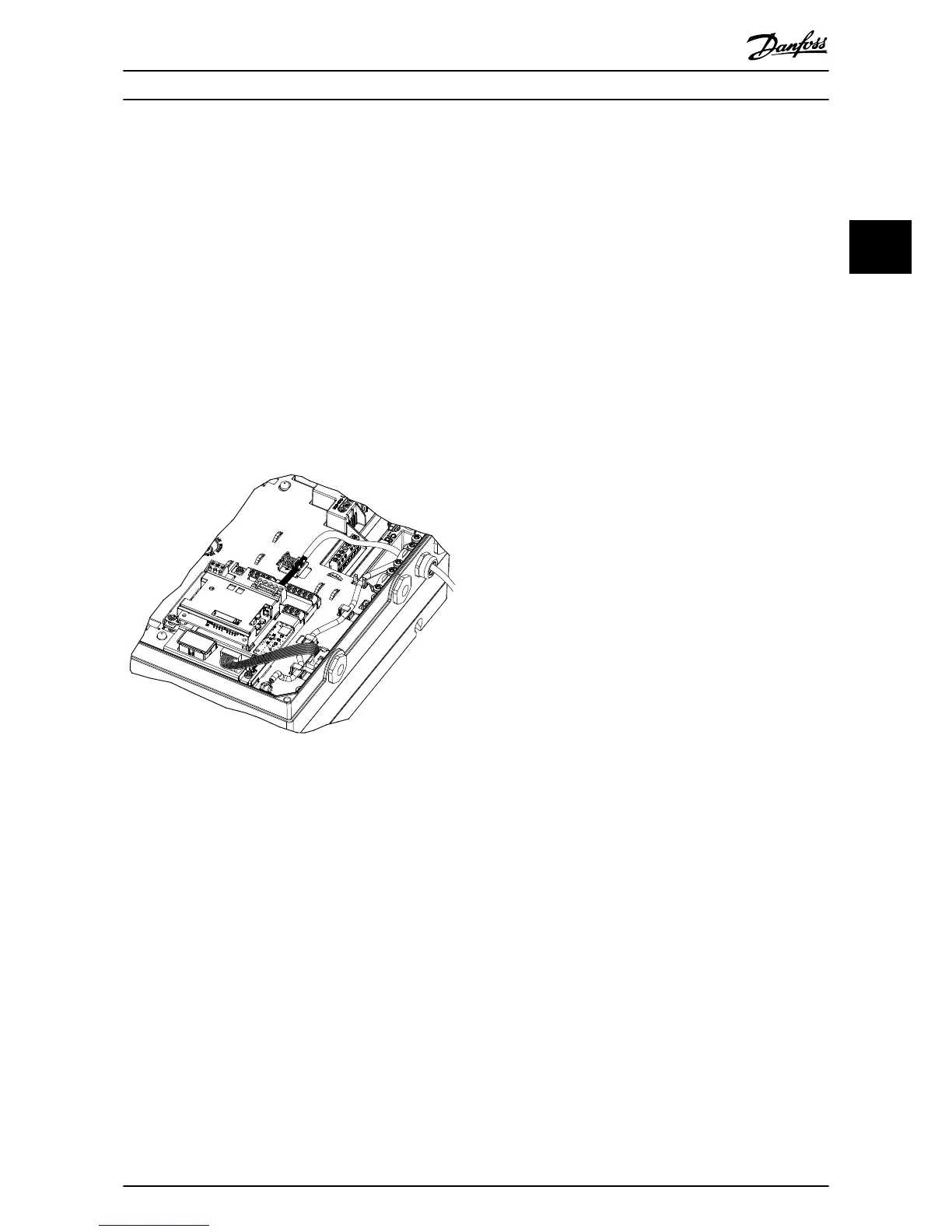
3. Connect the eldbus cable wires to the terminals
according to the colour code of the wires, see
Illustration 3.10.
4. To establish mechanical xation and electrical
contact between cable screen and ground,
position the stripped cable between the spring
loaded metal clamps.
Illustration 3.13 PROFIBUS Wiring for FCP 106, MH1–MH3
3.8 Reassembling Cover
1. Mount the new front cover and the LCP.
2. Attach the sticker with the correct product name
to the front cover.
3.9 Applying Power
Follow the instructions in the frequency converter
operating instructions to commission the frequency
converter. The frequency converter automatically detects
the PROFIBUS interface. A new parameter group (9-**
PROFIBUS) appears.
3.10 Checking Network Cabling
1. If the address has not been set via the address
switches, go to parameter 9-18 Node Address to
set the address.
2. Connect to a running PROFIBUS master.
3. Check that network cabling is correct:
3a Check that the net status LED ashes
green in any pattern, except search baud
rate, see Table 4.2.
3b Check if parameter 9-63 Actual Baud Rate
shows the same baud rate as the
PROFIBUS master.
3c Check that the bit baud rate search in
parameter 9-53 Probus Warning Word is
not active.
Installation Installation Guide
MG33C602 Danfoss A/S © 07/2015 All rights reserved. 13
3 3

 Loading...


