2
FRCC.EI.024.A1.02 © Danfoss Commercial Compressors 10/12
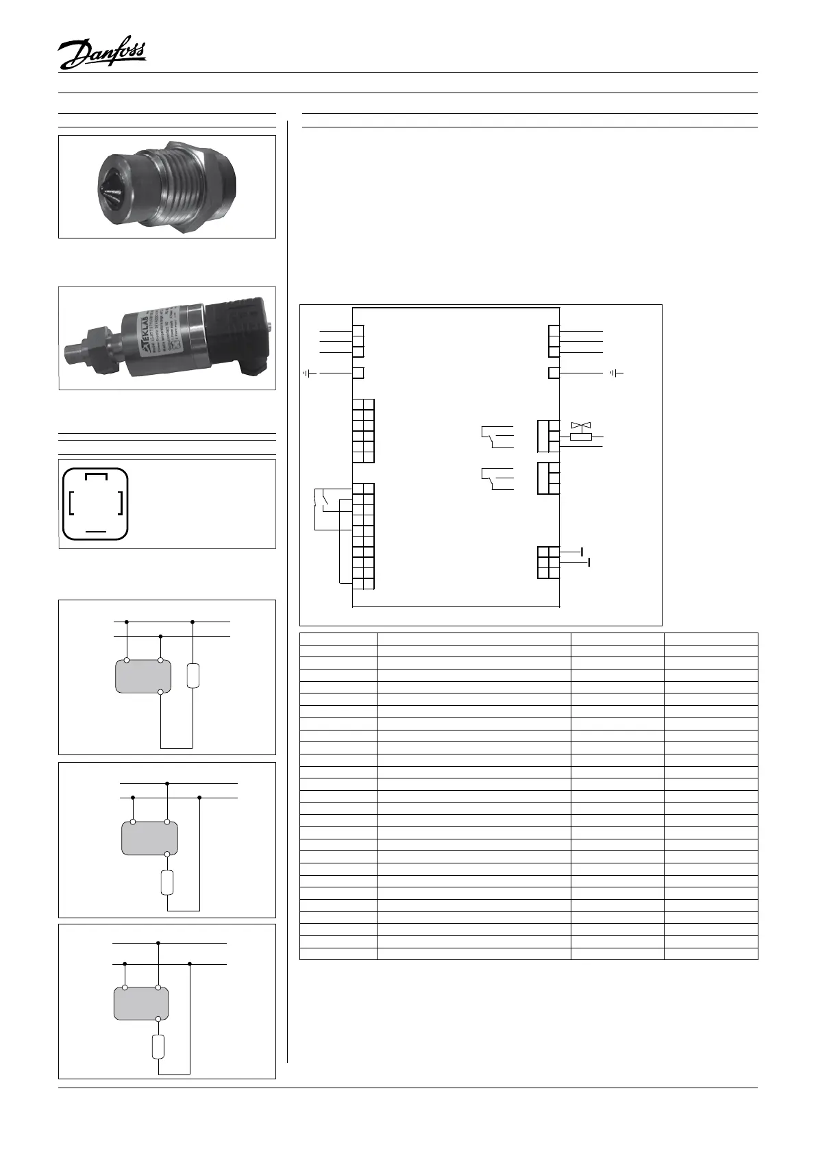
Basic connections
- Depending on the frequency converter
version, the physical position of individual
connectors may dier from below diagram.
- Always make sure that the compressor termi-
nals T1, T2, T3 are connected to the frequency
converter terminals 96, 97, 98 respectively.
- The compressor motor cable must be shielded
and the armoured part must be connected to
ground on both cable ends; at the side of the
compressor and at the side of the frequency
converter.
- Use an EMC cable gland for cable installation and
perfect grounding; The metallic terminal box of
the compressor has a paint-free surface around
the connection hole for better conductivity.
- A low pressure safety switch is mandatory
to avoid compressor vacuum operation.
- At start-up, verify that the compressor rotates
in the right direction and pumps.
230 V or 24V
~
2 A max
RELAY
1
L1 91 L1 W 98 T3
L2 92 L2 V 97 T2
L3 93 L3 U 96 T1
95 PE PE 99
39 39 Ana out COM
42 42 Ana out +
50 50 Ana out +10 V NC 03
53 53 Ana in 0 ± 10 V NO 02
54 54 Ana in 0 ± 10 V COM 01
55 55 Ana in COM
NC 06
NO 05
12 12 +24V COM 04
13 13 +24V
18 18 Dig in
19 19 Dig in
27 27 Dig in/out
29 29 Dig in/out
32 32 Dig in N- RS485 69 69
33 33 Dig in P+ RS485 68 68
20 20 Dig in COM COM RS485 61 61
37 37 Dig in
RELAY
Legends:
Ana: Analogue
Dig: Digital
in: Input
out: Output
COM: Common
NC: Normally-closed
NO: Normally-open
Open loop Process loop
91, 92, 93: 3 Phase mains input X X
95: Earth X X
39, 42 Analogue output - -
50: Analogue output - -
53: PLC+ (0 to 10 V) X -
54: Sensor - - X
55: PLC- X -
12: HP/LP switch X X
12: External On/O (NO) X X
13: Factory bridged to 37 X X
13: Sensor + - X
18: External On/O (NO) X X
19: Digital input - -
27: HP/LP switch (NC) / safety devices X X
29: Digital input/output - -
32, 33 Digital input - -
20: Digital input Common - -
37: Factory bridged to 13 X X
98: To compressor terminal T3 X X
97: To compressor terminal T2 X X
96: To compressor terminal T1 X X
99: To compressor earth connection X X
02, 01: Relay 1 to oil solenoid valve X X
06, 05, 04: Relay 2 - -
69, 68: RS485 Bus - -
61: RS485 Bus Common - -
The CDS303 frequency converter is factory pre-
set with parameters for the open loop control
principle. The process loop control principle
can be selected by changing parameters in the
«Quick menu».
Open loop:
0 - 10 V control
Frequency converter in slave mode
Process loop:
4 - 20 mA control
Frequency converter under own PID controller
Oil level switch assembly
Electrical connections / Wiring
Install the screw-in optical part on oil level
switch port. (Factory preset for manifold version
VZH compressor.)
3
1
4
2
1: Power supply wire
2: Power supply wire
3: Output wire
4: Not used
Install the electrical part on optical part. Make
sure the cable outlet downside vertically
See at the correct diagram corresponding
to different power supply models for proper
wiring
1
OVDC
24VDC
2
3
Sensor
External
Load / Relay
24VDC MODEL
1
OVAC
24VAC
2
3
Sensor
External
Load / Relay
24VAC MODEL
1
N
L
2
3
Sensor
External
Load / Relay
230VAC MODEL
- : Optional connection X : Mandatory connection
Instructions
 Loading...