Instructions
2 | AN233086441027en-000501 - 8510280P01AA
© Danfoss | DCS (CC) | 2021.03
1 – Introduction
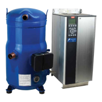
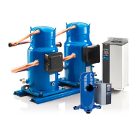
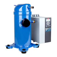
These instructions pertain to the VZH028-
VZH065 variable scroll compressors used for air-
conditioning and reversible heat pump systems in
residential applications. They provide necessary
information regarding safety and proper usage of
this product.
2 – Handling and storage
• Handle the compressor with care. Use the
dedicated handles in the packaging. Use the
compressor lifting lug and use appropriate and
safe lifting equipment.
• Store and transport the compressor in an
upright position.
• Store the compressor between -35°C and 55°C
/ -31°F and 131°F.
• Don’t expose the compressor and the
packaging to rain or corrosive atmosphere.
3 – Safety measures before assembly
Never use the compressor in a flammable
atmosphere.
• The compressor ambient temperature may not
exceed 50°C during off-cycle.
• Mount the compressor on a horizontal flat
surface with less than 7° slope.
• When installing a compressor model VZH,
use equipment specifically reserved for HFC
refrigerants, which was never used for CFC or
HCFC refrigerants.
• Use clean and dehydrated refrigeration-grade
copper tubes and silver alloy brazing material.
• Use clean and dehydrated system components.
• The piping connected to the compressor
must be flexible in 3 dimensions to dampen
vibrations.
• The compressor must always be mounted
using the rubber grommets supplied with the
compressor.
4 – Assembly
• Slowly release the nitrogen holding charge
through discharge and suction ports.
• Connect the compressor to the system as soon
as possible to avoid oil contamination from
ambient moisture.
• Avoid material entering into the system while
cutting tubes. Never drill holes where burrs
cannot be removed.
• Braze with great care using state-of-the-art
Basic connections
- Depending on the frequency converter
version, the physical position of individual
connectors may differ from below diagram.
- Always make sure that the compressor
terminals T1, T2, T3 are connected to the
frequency converter terminals 96, 97, 98
respectively.
- The compressor motor cable must be shielded
and the armoured part must be connected to
ground on both cable ends; at the side of the
compressor and at the side of the frequency
converter.
- Use an EMC cable gland for cable installation and
perfect grounding; The metallic terminal box of
the compressor has a paint-free surface around
the connection hole for better conductivity.
- A low pressure safety switch is mandatory
to avoid compressor vacuum operation.
- At start-up, verify that the compressor rotates
in the right direction and pumps.
Oil level switch assembly
Install the screw-in optical part on oil level switch
port. (Factory preset for manifold version VZH
compressor.)
Install the electrical part on optical part. Make
sure the cable outlet downside vertically.
* For LC-PR, make sure the cable outlet downside
or upside vertically.
L1
L2
L3
N
External
Load / Relay
LC-XN
12
3
230VAC
24VAC
0VAC
12
3
24VAC
External
Load / Relay
LC-XN
24VDC
0VDC
12
3
24VDC
External
Load / Relay
LC-XN
L / 24V
N / 0V
14
23
External
Load
LC-PR
LC-XN
LC-PR
3
1
4
2
1: Power supply wire
2: Power supply wire
3: Output wire
4: Not used
3
1
1: Power supply (L or 24V)
2: Output NO CONTACT
3: Power supply (N or 0V)
4: Output COMMON
Electrical connections / Wiring for Oil level sensor
See at the correct diagram corresponding to different power supply models for proper wiring
 Loading...