34
Mounting and installation instructions, continued
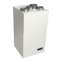
Fresh air duct
connection
On the air inlet side is an opening for connection of a fresh air duct. The opening is
covered by a cover which has to be removed before connecting the fresh air duct.
If a fresh air duct is connected, we recommend that a fan is mounted for drawing out
the extra air in order to maintain a comfortable under pressure in the room and to avoid
moist and chlorine-containing vapours diffusing through the walls.
An external fan for removal of the extra amount of inlet air may be connected to termi-
nal points 7 and 8 on the PCB together with the fresh air damper. The external fan will
then start along with the fresh air damper. Maximum load on points 7 and 8 is 6A.
Maximum quantity
of fresh air
The max. quantity of fresh air should not exceed the values mentioned in the table be-
low.
Too much fresh air, particularly in winter, could lead to ice formation on the evaporator
and cut-out by the low-pressure pressostat.
CDP 75 CDP 125 CDP 165
m
3
/h 225 375 540
Water heating coils
The CDP 75, 125 and 165 can be fitted with water heating coils.
The heating coil is designed for installation in the air outlet duct. The heating coil has
duct connection spigots allowing direct fixing to the connections of the units.
The technical specifications for the water heating coils are given in the table on page
110.
Connection of
water heating coils
The control signal for control of the heating coil takes place through the terminals 1 and
2 and the outlet is 230 V/1A.
The control is prepared for connecting a room thermostat to the terminals 5 and 6. The
outlet of the thermostat is 12 V. The bridge between terminal 5 and 6 has to be re-
moved before connecting the thermostat.
If the control signal is used for control of the water heating coil and a connected room
thermostat, the water heating coil will always be cut out when the power to the unit is
turned off. When the water heating coil is connected as described above, it may be
connected and disconnected by the push button with the fire symbol .(See section 4.3
Push button indications).
Water-cooled
condenser
To lead away any excess heat from the unit, a water-cooled condenser may be fitted
allowing transfer of the excess heat to the pool water instead of the room air.
CDP 75, 125 and 165 with water-cooled condenser are supplied with cupper coupling
pipes (Ø15 mm). The coupling pipes can be coupled together with PEX pipes by
means of clamping ring fittings in cases where copper pipes are not required.
The technical specifications for the water-cooled condenser are shown in the table on
page 112.
Continued overleaf
 Loading...