11
and restrict the metering device.
Piping must be supported within 18” (457 mm) of the inlet and outlet connections. The inlet connection
is located on the top header of all units. The discharge outlet is located at the bottom of the header.
Discharge line pressure drop should not exceed 6 PSI (41 kPa) for R-407C and 9 PSI (62 kPa) for
R-410A. Recommended gas velocity for proper oil return is 1,000 FPM (5.1 m/sec). Slope horizontal
lines downward in the direction of the refrigerant ow (1/2” (12 mm) for every ten feet (3 m) of line
length). Discharge lines do not require insulation but due to the high temperatures of the refrigerant
inside the line, the pipes may be insulated to protect against burns to individuals near or around the
lines.
2.7.3 Liquid Lines
Liquid line size is determined by pressure drop and velocity. The liquid line pressure drop for R-407C
should not exceed 5 PSI (35 kPa) or 9 PSI (62 kPa) for R-410A. The recommended liquid velocity
should be between 200 and 300 FPM (1 to 1.5 m/sec). To avoid excessive liquid line pressure drop,
the air cooled condenser should be located above or at the same level as the evaporator. Condenser
installations more than 15 feet below the evaporator are not recommended. Insulation of liquid lines is
not required but can be useful in preventing excessive sub-cooling or ashing on long exposed pipe
runs.
2.7.4 Suction Lines
Some applications call for the compressor to be mounted as part of the condenser (more commonly
referred to as a condensing unit). Condensing units require eld piping of liquid and suction lines.
Suction lines are trapped similarly to discharge lines. Common practice for suction line selection and
installation should be followed. Suction lines should always be insulated.
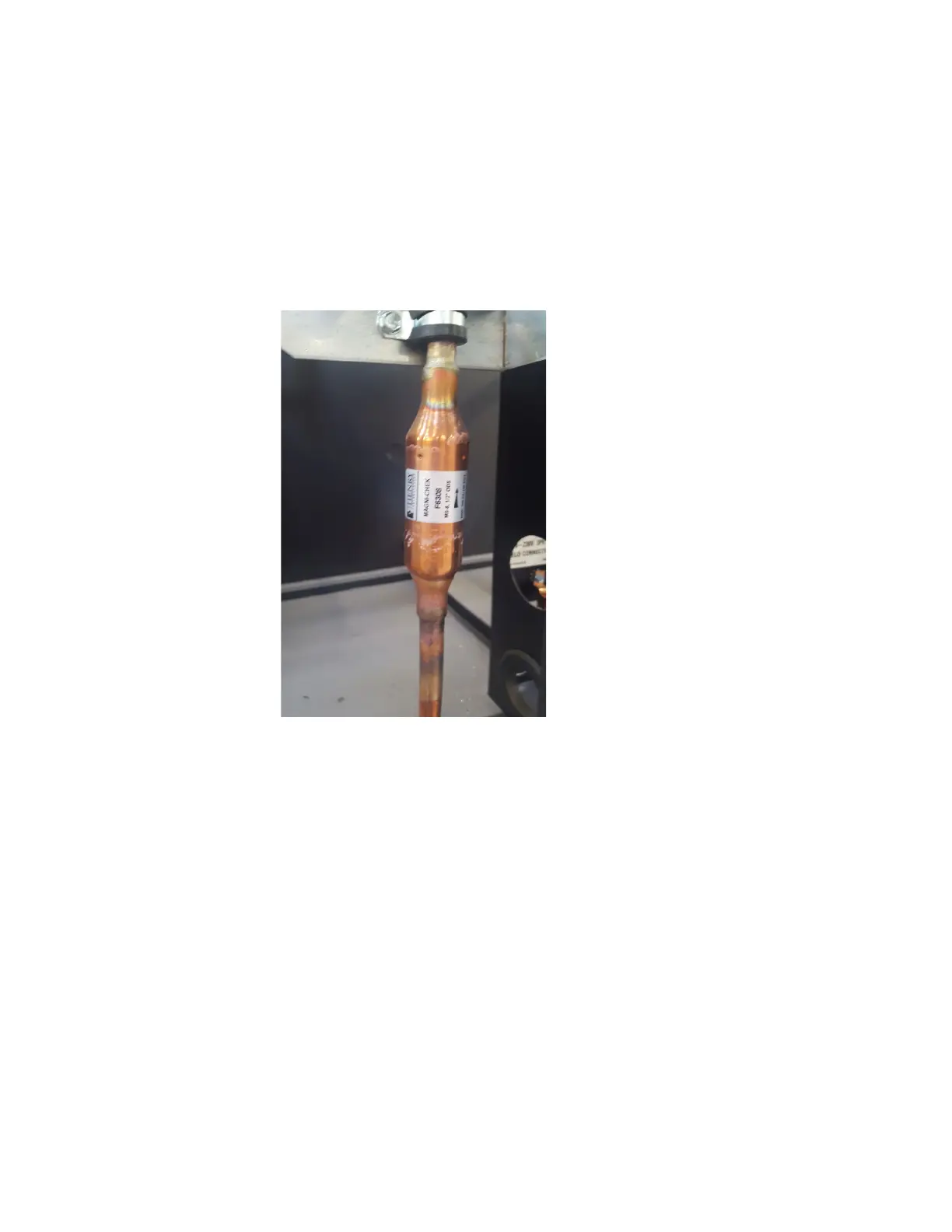
Note: Picture is only intended to show an example of a common check valve installation. It may not
represent your specic unit, check valve size, location or orientation.

 Loading...