8
2.4 Rigging
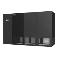
Move the unit in its upright position to the installation site. It is recommended that the unit be protected
from damage to the decorative doors during any storage or moving. Removal of the decorative doors
is easily accomplished and may be done without moving the equipment.
The shipping skid should be left in place if the unit is being moved with a forklift. If the unit is being lifted,
use spreader bars to prevent damage to the doors and panels.
The unit has 3/4” (19mm) holes in the shipping skid to which casters with 3/4” (19mm) stems can be
attached. This allows easy movement down halls, into elevators and through doorways. If clearance
is a problem the casters may be inserted directly into the bottom of the 1” (25mm) tubular steel corner
posts at the bottom of the unit.
WARNING: Improper lifting or moving of the equipment may result in damage to the
decorative doors, panels or frame members.
2.5 Locating the Unit
Verify that the oor is level, solid and sucient to support the unit. When installing the unit, sucient
space must be allowed for airow clearance, wiring, plumbing and service access. It is recommended
that each side and front have a clearance of at least 36” (914mm) to allow the doors to swing open and
for servicing the unit.
The doors on some sides may not require as much service clearance. Refer to the particular unit
component breakdown drawings for assistance. Rear clearance is not required, but 1” to 2” (25 to
50mm) of clearance is suggested.
For the best air distribution, the unit should be centered against the longest wall, distributing the cold
air as close to heat load as possible, unless the unit is ducted. The unit should not be placed near any
corner of the room or at the end of a long, narrow room. Install the units as close as possible to the
largest heat load. Multiple units should be evenly spaced, as far apart as possible. It is recommended
to install an under-oor water detection system.
Note: Condensation formation and frequent humidier ushing are normal functions
of this equipment. Proper drain connections must be made to ensure proper removal.
Unit will require water connections for condensate removal and possibly for humidier
makeup water, water/glycol and hot water. Installation of units above equipment that
could sustain water damage should be avoided.
2.5.1 Downow Units
Downow units will typically sit on an elevated ooring system known as a raised oor. The unit
discharges air downward which pressurizes the raised oor and channels upward through perforated
oor tiles. Location and quantity of perforated tiles will dictate proper air distribution. If the raised oor
is strong enough to support the unit and local codes permit, the unit can be placed directly on top with
cutouts made for the discharge openings.
Verify that the raised oor has been properly sized for the unit’s airow and the room is free of airow
restrictions. Perforated oor tiles in the raised oor should ensure minimal pressure loss. The raised
oor must provide 12” (305 mm) of clearance. Ensure that there is adequate clearance above the unit
for service, such as replacing lters.
There may be additional support required in the form of adjustable jackstands. These are adjustable,
threaded leveling rods which support the unit in each of the corners and in the center on longer length

 Loading...