17
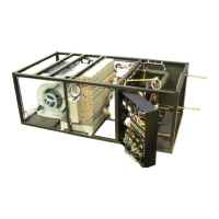
4.0 INSTALLATION OF REMOTE OUTDOOR HEAT EXCHANGER
Air cooled condensers and fl uid coolers have individual Installation, Operation and Maintenance
manuals which should be referred to for more complete details.
4.1 Rigging
This section covers outdoor condensers/condensing units and fl uid coolers. For indoor condensers
and condensing units refer to section 1.3.4. Outdoor heat exchangers should be moved to their
(typically rooftop) mounting location using a crane or fork lift. Each fan section have supports with
lifting holes at the top.
Do not lift with a choke sling around the unit. Spreader bars are recommended for lifting multiple fan
units. Under no circumstances should the coil headers or piping be used for lifting the unit. Ideally,
the unit should be kept in its shipping crate until it is ready to be set in place.
4.2 Leg Assembly
Most condensers and condensing units matched up with Mini Ceiling units are self-contained and
require no fi eld modifi cation to the mounting legs. Larger condensers/condensing units and fl uid
coolers, size “06” and larger, have legs that must be unbolted from their collapsed shipping position
and extended prior to placing the unit on its pad.
Each leg extends down approximately 18” and reattaches using the same bolts, the bolts are placed
through the lower set of holes on the bracket.
Note: Failure to extend the legs will result in poor air distribution over the cooling coil resulting
in signifi cant capacity reduction and potential high discharge pressure problems.
Concrete pads or a rail system are often used to provide support for the heat exchanger. Bolt holes
in the bottom of each leg can be used to anchor the unit.
4.3 Locating the Remote Heat Exchanger
The remote heat exchanger must be located in
an area that will ensure free air fl ow into and out
of the heat exchanger plus adequate service
access clearance. Short circuiting of the air fl ow
or the intake of warmer air from another unit
will seriously degrade the performance of the
air cooled heat exchanger.
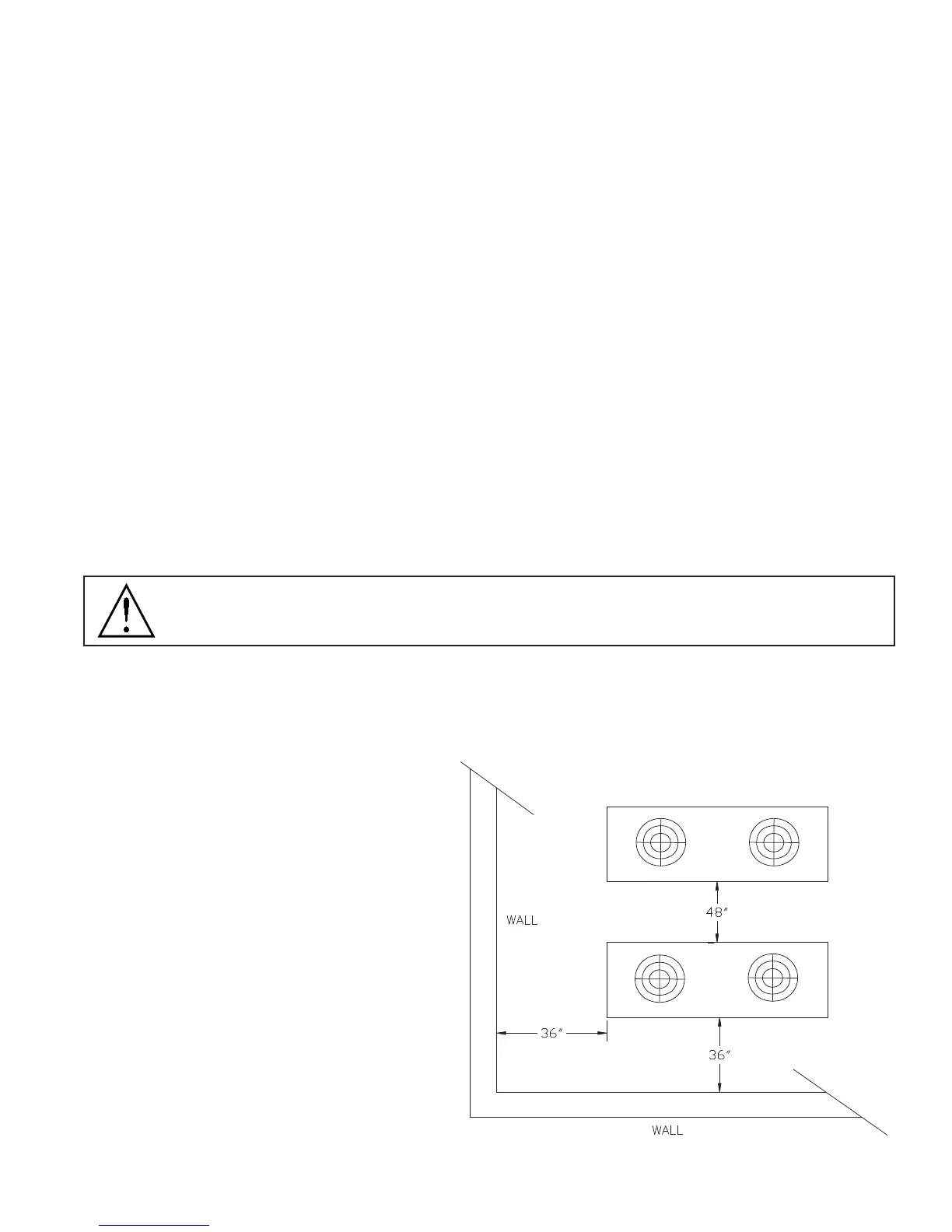
Do not locate the heat exchanger in a location
that is bordered by tall obstructions (i.e., higher
than 10 feet) on no more than two sides. See
Figure at right for minimum clearance from
obstructions and between units. With proper
clearance on all sides, two units can be placed
side by side. Additional units should be placed
at least 48 inches apart.