Datacom Systems Inc
SPAN and Multi-Link Aggregators/Regenerators • USERguide
12
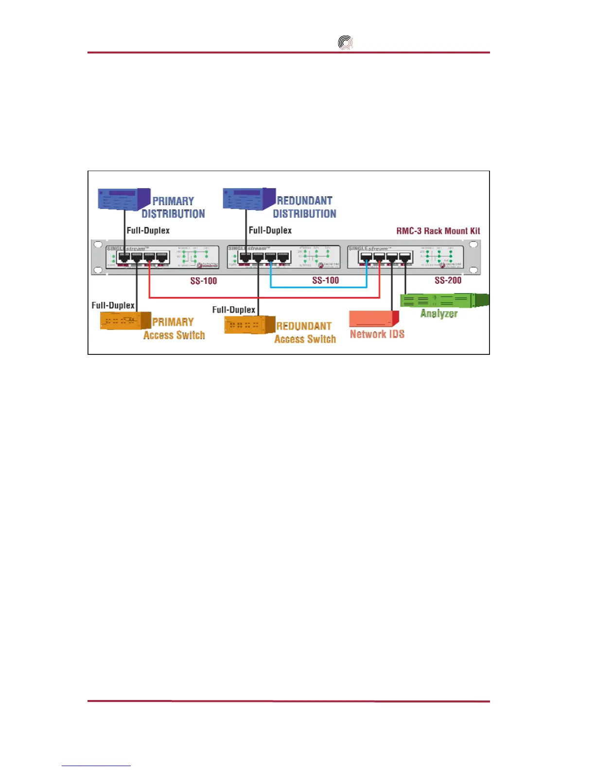
SS-200 Application & Hardware Installation —
The SS-200 is used primarily in conjuction with two SS-100s to monitor and anlay-
sis Primary and Redundant Distribution Networks.
Figure 2 depicts a typical set of
monitoring tools attached to a primary circuit that automatically switch to the redundant cir-
cuit allowing uninterrupted monitoring using only one network interface card (NIC) for each
monitoring device to see the combined traffic.
Figure 2 - SS-200 Connectivity Diagram
To connect the SS-200 into the network, refer to FIGURE 3 and follow these steps:
Step 1. Two power supplies are provided for the SINGLEstream
™
SS-100 and one power sup-
ply for the SINGLEstream
™
SS-200. Use of the second power supply is strongly rec-
ommended for the SINGLEstream
™
SS-100 to assure uninterrupted monitoring.
Connect both power supply barrel connectors into the POWER 1 and 2
ports, respec-
tively, of the SINGLEstream
™
SS-100. Plug the power Supplies into the external
power source, furthermore, connecting the second power supply to a different external
power source circuit than the first power supply eliminates power as a single point of
failure. The POWER 1 and 2 LEDs illuminate indicating power 1 and 2, respectively,
are on. Either LED not illuminated indicates a defective power source and immediate
replacement is required to insure redundant power integrity.
IMPORTANT: The maximum length of 100 meters must not be exceeded between end-points.
Step 2. Designate one SINGLEstream
™
SS-100 primary and the other redundant. Connect the
primary network cables to the primary SINGLEstream
™
SS-100 RJ45 port NETWORK A
connector. The NETWORK-A LINK LED illuminates indicating link has been established
between the NETWORK A connector and primary NETWORK A device.
NOTE: Let the “LINK” LED be your guide.
If you are properly connected,
NETWORK-A
and
NET-
WORK-B
“
LINK
”
LEDs
remain illuminated simultaneously.