Datacom Systems Inc
SPAN and Multi-Link Aggregators/Regenerators • USERguide
23
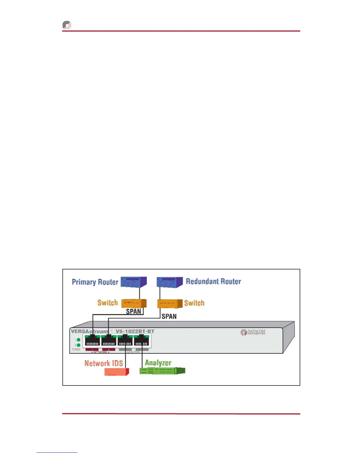
Figure 15 - VS-1022BT-BT Hardware Installation
Primary/Redundant Router Application — shown in Figure
15, focuses on monitoring and analyzis of the
SPAN output of a Primary and
Redundant network aggregated into one single stream of data. This VS-1022SX-SX is
similiar to other VERSAstream
™
SPAN series installations:
connecting the second power supply to a different external power source circuit
than the first power supply eliminates power as a single point of failure. The
POWER 1 and 2 LEDs illuminate indicating power 1 and 2, respectively, are on.
Either LED not illuminated indicates a defective power source and immediate
replacement is required to insure redundant power integrity.
2. Connect one network device duplex-SC plug to the FIBERtap
™
duplex-SC B
OUT and AINconnector.
3. Connect the other network device duplex-SC plug to the FIBERtap
™
duplex-SC
A OUT and B IN connector.
4. Using either a DRL490-2m (62.5 micron for SX) Cable or a DRL491-2m (9
micron for LX) Cable, connect the FIBERtap
™
duplex-SC A OUT and B OUT
connector to both of the VERSAstream
™
duplex-LC
NETWORK
ports. The LED
associated with each
NETWORK
duplex-LC jack is solid green indicating light sig-
nal has been detected on the Rx
NETWORK
ports.
5. Connect analysis devices to the VERSAstream
™
duplex-LC
MONITOR
ports. Two
DRL494–2m cables are provided to connect analysis SC ports to the duplex-LC
MON-
ITOR
ports. The LED associated with each
MONITOR
duplex-LC jack is solid green
indicating when light signal has been detected on the respective Rx
MONITOR
port.