DS2 Instruction Manual
8. DIAGNOSTIC FUNCTIONS AND LED INTERFACE ERROR SIGNALLING
8.1. Device status visualisation
The operator can verify the device functioning status using the three LEDs present the receiver unit and
the one present on the emitter unit.
The meaning of the LEDs present of the receiver unit (RX) depends on the light grid operating mode.
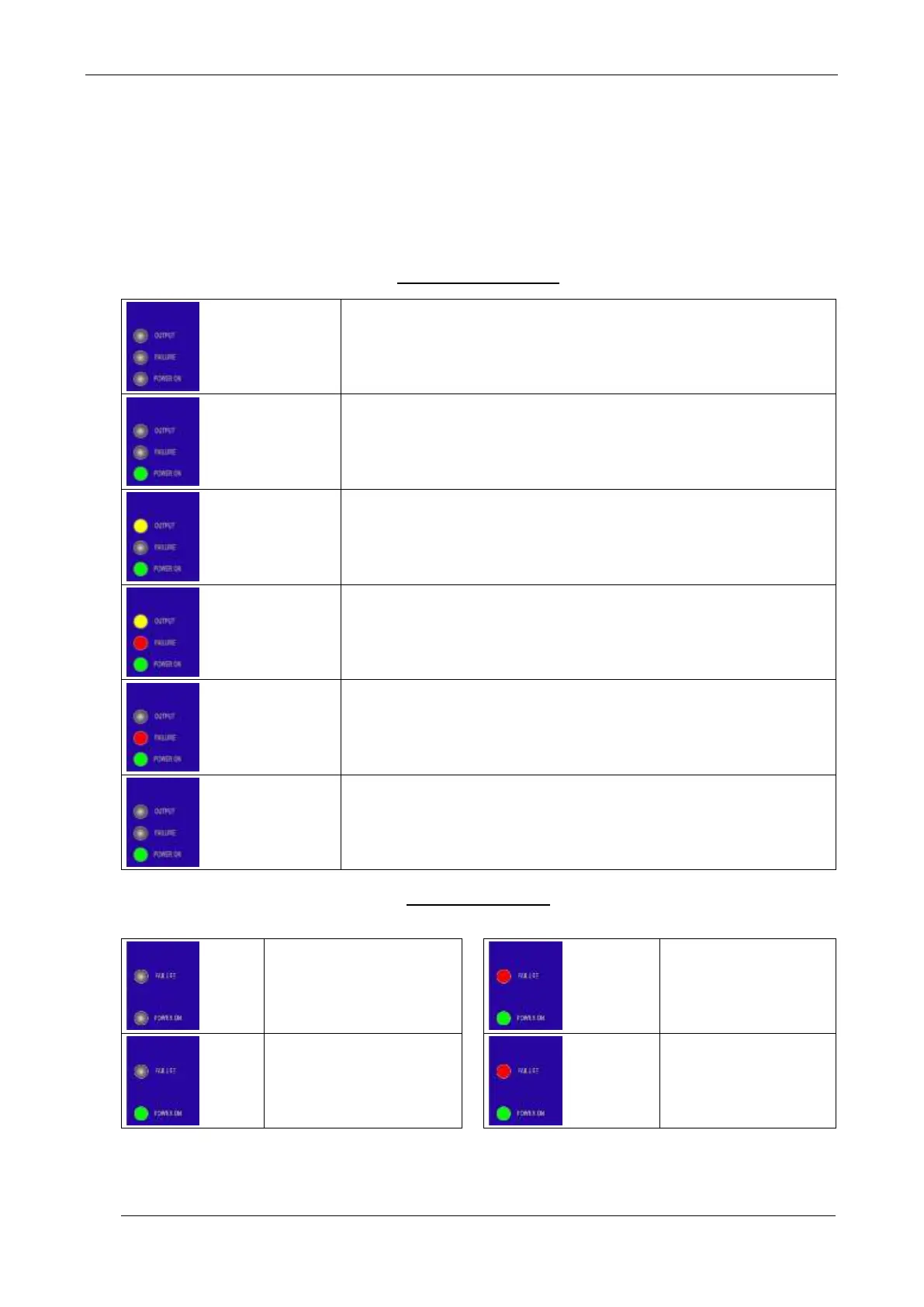
RECEIVING UNIT (RX)
- No power supply.
- Microprocessor in the reset condition.
- Presence of object inside sensitive area or units misaligned.
- Short-circuit signalling on switching output
- Generic anomaly on RX unit
- Critical alignment of the TX and RX units or weak received signal.
EMITTER UNIT (TX)
- No power supply.
- Microprocessor in the
reset condition.
- Generic anomaly of
the TX unit
- No synchronism
between RX and TX
units
Yellow ON
Red blinking
Green ON
OFF or ON
OFF
Green blinking

 Loading...