DS2 Instruction Manual
7.3.2 Command packet description:
a. Synchronism command - 0x43 (‘C’ ASCII)
The host can use this command when connected to DS2 to obtain the local/remote configuration
parameters. If the serial transmission speed is missing, all known baud-rates can be tested until the
connection is established.
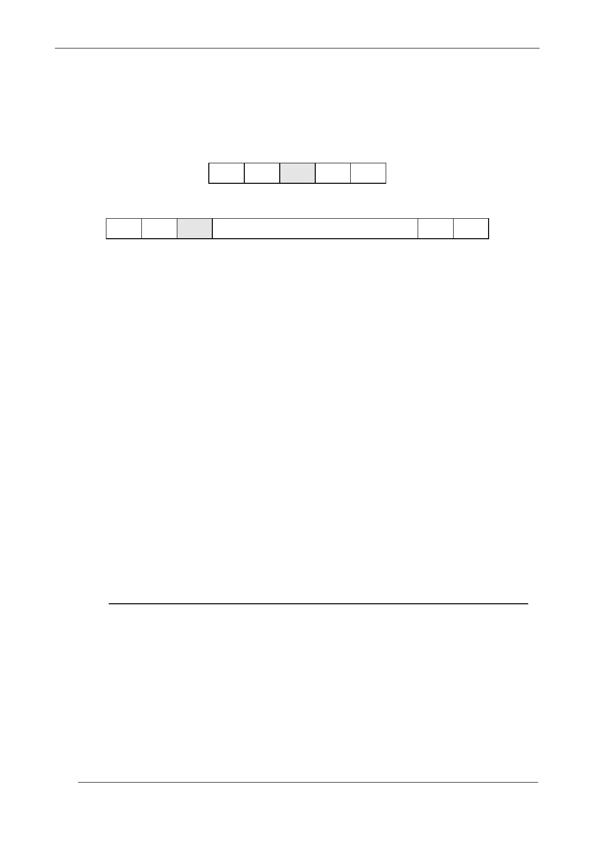
Host sends:
DS2 replies:
N = 1 byte with photoelement number (84, 126, 168 or 231)
L = 1 byte with the local configuration status (Dip-switch)
bit 0 = OutDelay 4B - Output Delay (No Delay/100ms Delay)
bit 1 = OutMode 3B - Output Mode (NO/NC)
bit 2 = TeachMode 2B - Teach-in Mode (Absolute/Relative)
bit 3 = TeachAcc 1B - Teach-in active (Inactive/Active)
bit 4 = MeasAna 4A - Measurement Analysis Mode (BotTop/Total)
bit 5 = MeasRef 3A - Measurement Reference Beam (Bottom/Top)
bit 6 = SerMode 2A - Serial Output Mode (Binary/ASCII)
bit 7 = ProgMode 1A - Programming Mode (Local/Remote)
rrrrrrr = 7 bytes with the remote configuration status
byte 1 = SerComm Serial Communication (1 = Active, 0 = Inactive)
Short Protocol (bit 7 = 1 Enable, bit 7 = 0 Disable)
byte 2 = BaudRate Baud-rate (range 0 = 9600, 1 = 19200, 3 = 38400 4 = 57600)
byte 3 = MeasAna1 Measurement Analysis Mode 1 (see below)
byte 4 = MeasAna2 Measurement Analysis Mode 1 (see below)
byte 5 = SendType Data Sending Type (0 = Cyclical, 1 = On Change or 2 = On Request)
byte 6 = DipSw Remote setting by virtual dip-switches (only partially applicable)
byte 7 = OutputDelay Output Delay 0-200ms
x = checksum (complement to one of the Length, Type and Data field bytes sum)
Numeric value associated to measurement type:
0 = Measure disabled
1 = Complete beams status array
2 = Top beam dark
3 = Top beam light
4 = Bottom beam dark
5 = Bottom beam light
6 = Middle beam dark
7 = Middle beam light
8 = Total beam dark
9 = Total beam light
10 = Total contiguous beam dark
11 = Total contiguous beam light
12 = N. of transitions dark
13 = N. of transitions light
Remote configuration state (Virtual Dip Switch)
bit 0 = OutDelay 4B - Output Delay (No Delay/Delay)
bit 1 = OutMode 3B - Output Mode (NO/NC)
bit 2 = TeachMode 2B - Teach-In Mode (Absolute/Relative)
bit 3 = TeachEna 1B - Teach-In Enable (Disable/Enable)
bit 4 = MeasAna 4A - n. a.
bit 5 = MeasRef 3A - n. a.
bit 6 = SerMode 2A - Serial Output Mode (Binary/ASCII)
bit 7 = ProgMode 1A - n. a.
 Loading...