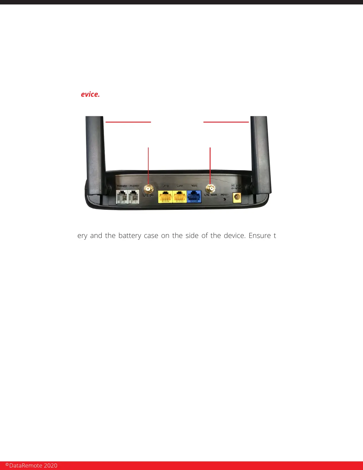
b. LTE Antennas connect to outer two (2) coaxial connectors on the DataRemote
CDS-9010 device. NOTE: DO NOT try to remove the WiFi antennas, there come
attached to the device.
2. Place the battery and the battery case on the side of the device. Ensure the power cable are
supported to prevent damage to the molex power plug.
3. Once the DataRemote CDS-9010 device is positioned to achieve the best signal strength
possible: high on the wall with antennas facing up, use your eye and torpedo level to install the
DataRemote CDS-9010 device in the selected location. Dress and secure the DataRemote
CDS-9010 device's power cable's path neatly. If there are questions about the unit's placement,
please contact Installation Support.
4. Verify correct LED lights on the DataRemote CDS-9010 device.
NOTE: any variations from the above, see the troubleshooting guide attached separately in
your Work Order and/or call your respective Installation Support Line.
1. Phone 1-2 indicators should be either solid green (On-Hook) or flashing green (Off-Hook/Busy).
Call DataRemote Installation Support if LED indicators for the FXS are not lit. Once the lights above
have been verified, use a butt set (or an analog test phone if your model butt set doesn't have an
RJ-11 modular connection) to place a test call from the phone 1 jack to your cell phone if line one is
a voice line.
2. IMPORTANT: You MUST complete the call by answering it; otherwise the device won't
register the test call event in the server logs, which is used for install validation.
TESTING VOICE LINE.
CDS-9010 DEVICE ASSEMBLY/PRE-TEST + FIRE PANEL LOCATION
PHASE 1 (continued)
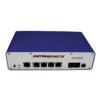
Cellular antennas connectors
WiFi antennas
Page 16
Revision No. 004 April 2020